Lotus Elise / Lotus Exige. Manual - part 47
Page 7
Lotus Service Notes
Section FJ
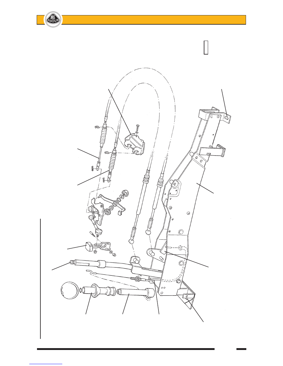
Gearchan
ge Mechanism
& Mou
nting Frame (
prior May '07)
Gear Lever
Inertia weight
Shift cable
Crossgate cable
Lift tube
Transmission
abutment
bracket
Lift tube
adaptor
Reverse
selector
cable
(6-speed only)
Fixing to
pl4705mtx
seat front
Reverse gate
crossmember
stop arm
Gear lever
mounting frame
Fixing to seat
rear crossmember