Lotus Eleven/Elise/Exige. Manual - part 76
 

  Index      Lotus     Lotus Eleven/Elise/Exige (engine 1ZZ/2ZZ/1ZR) - service repair manual 2004 year


Search            


Content   ..  74  75  76  77   ..


Lotus Eleven/Elise/Exige. Manual - part 76


Lotus Service Notes

     Section LJ

Page 7

9.

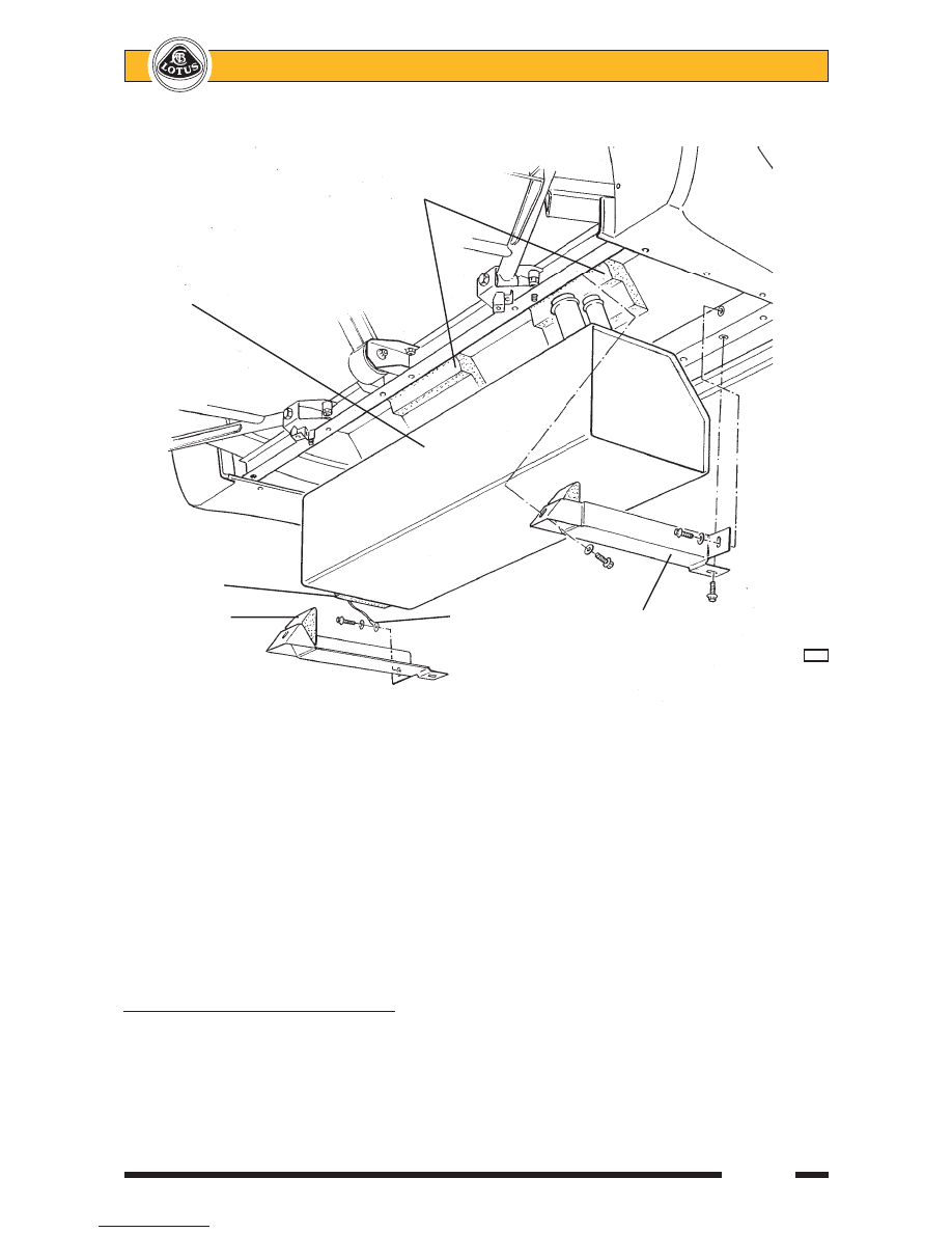
Ensure the pump/sender unit is fitted into the into the tank, with the earth braid fitted onto the '10 O'clock'
position pump mounting stud.

10.

Loose fit the LH tank mounting cradle ensuring that the earth braid is fitted beneath the head of the
horizontally disposed front fixing bolt.

11.

Feed the LH end of the tank into the cradle, and raise the tank into position taking care not to trap or pinch
the fuel pipes or wiring harness.  Retain with the RH cradle, noting that no washer is fitted at the horizon-
tally disposed front fixing point.  Torque tighten the cradle fixing bolts to 24 Nm.

12.

Continue the installation in reverse order to removal, and ensure that the 'shear panel' is fitted beneath
the fuel tank bay before driving the car.

LJ.5 - FUEL PUMP/SENDER ASSEMBLY

The combined fuel pump/gauge sender unit is mounted in the left hand end of the tank top surface.  A

removeable panel is provided in the top of the chassis crossmember in the cabin, which provides access to the
fuel pipe connections and harness connector, but if the pump/gauge sender unit is to be replaced, the tank
must be removed from the chassis (see sub-section LJ.4).

For fuel pump test procedures, refer to Toyota 2ZZ-GE Engine Repair Manual, publication RM733E.

   Polypropylene saddles

Fuel tank

Foam sponge

Rubber wedge

Earth braid

Support
cradle

                         L59b


Lotus Service Notes

     Section LJ

Page 8

To Remove Pump/sender Assembly
1.

Remove the fuel tank (see sub-section LJ.4).

2.

Release the eight nuts securing the clamping ring, and carefully withdraw the pump assembly from the
tank.  Immediately seal the tank aperture to reduce the fire hazard and prevent dirt ingress.

3.

For permitted disassembly of the pump unit, refer to Toyota 2ZZ-GE Engine Repair Manual, publication
RM733E.

4.

To refit the pump assembly, renew the rectangular section sealing ring before carefully feeding the sender
float arm in through the tank aperture.  Orientate the unit with the breather spigot pointing inboard, and fit
the clamping ring with the location tab engaged with the recess in the pump top moulding.  Fit and secure
the eight M6 washers and nuts.

5.

Refit the fuel tank into the car (see sub-section LJ.4).

6.

Connect the fuel feed pipe and retain with the spring clip.  Connect the breather pipe to the spigot on the
pump top plate.  Fit the harness plugs to the pump/sender connector, and to the pressure sensor.

LJ.6 - CHARCOAL CANISTER

In order to prevent fuel vapour venting from the fuel tank to atmosphere, the breather pipe from the tank

is routed to a canister filled with activated-charcoal, which absorbs and stores the fuel vapour when the engine
is stopped.  When the engine is running, the canister is connected to the depression in the intake plenum via a
port on the inlet manifold such that fresh air is drawn through the canister to purge the charcoal of its absorbed
fuel, with the resultant gas then consumed by the engine in the normal combustion process.

Charcoal Canister

This is mounted at the right hand front corner of the engine bay via a bracket fixed to the bulkhead.  Fuel

vapour from within the tank and collected from a spigot on the fuel pump/sender top plate, is routed via a
roll-over valve (to prevent fuel spillage if the car is inverted) mounted on the charcoal canister bracket, to the
canister port labelled ‘tank’.  This port is extended within the canister to the underside of the charcoal bed,
below which is a reservoir to collect any liquid fuel.  A second port on the canister ('vent') connects the top side
of the charcoal bed to atmosphere.  In this way, vapour from the fuel tank is cleansed of fuel by the charcoal
bed before venting to atmosphere.

The third, 'purge' port, controlled by a solenoid valve mounted on the air cleaner housing, connects the

underside of the charcoal bed with a port on the engine inlet manifold.  The solenoid valve is opened during
certain engine running conditions in order to allow intake depression to draw fresh air through the vent pipe and
charcoal bed, cleansing the charcoal of fuel before consuming the resultant vapour in the normal combustion
process.  In this way, the charcoal is prepared for further vapour absorption.

Control System

The canister purge valve is controlled by the engine management ECU, which keeps the valve closed

(unenergised) when the engine is cold or idling in order to protect the catalyst and maintain idle quality.  At
normal running temperatures and engine speeds above idle, the ECU monitors other running conditions and
management system stati, and when appropriate conditions pertain, the ECU will apply a duty cycle to the
valve in order to regulate the amount of purging allowed dependent on the amount of vapour in the canister.

Page 1


Lotus Service Notes   


    Section MP


ELECTRICS

SECTION MP


      Sub-Section         Page


Cobra Vehicle Security Alarm (prior '08 M.Y.)   


MP.1   

2


Central Door Locking  


MP.2   

6


Electric Windows 


MP.3   

7


Switches & Instruments - Driver's Information  


MP.4   

8


Component Location & Fuse Ratings   


MP.5   

14


Audio Equipment 


MP.6   

16


Battery, Battery Cables & Earthing Points 


MP.7   

17


Wiper Mechanism   


MP.8   

20


Harness Routing 


MP.9   

21


Front Lamp Assemblies 


MP.10   

22


2006 M.Y. Supplement 


MP.11   

25


2008 M.Y. Supplement  (incl. PFK alarm system) 


MP.12   

28


2011 M.Y. Supplement 


MP.13   

36


Updated 1st June 2010

Page 2


Lotus Service Notes   


    Section MP

MP.1 - COBRA VEHICLE SECURITY ALARM 

The Lotus Elise/Exige prior to '08 M.Y. is fitted as standard with a Cobra 8186 immobiliser/alarm which 

includes the following features:

Elise 111R U.K. approval to Thatcham category 1.

'Dynamic coding' of the transmitter keys; Each time the transmitters are used, the encrypted rolling code

is changed to guard against unauthorised code capture.

Automatic (passive) engine immobilisation to prevent the engine from being started.

Ingress protection using sensing switches on both doors, both front body access panels, and the engine

cover.

Personal protection by ‘on demand’ activation of the siren.

Selectable cockpit intrusion sensing using a microwave sensor.

Self powered siren to maintain protection if the vehicle battery is disconnected.

Alarm/owner transmitter programming using a Personal Identification Number (PIN).

Transmitter Fobs

Two  transmitter  fobs  are  provided  with 

the  car  to  operate  the  immobiliser/alarm 

system.    The  two  transmitters  should  be 

kept  separate,  and  a  replacement  obtained 

immediately  after  any  loss  to  ensure  that  a 

spare is always available.

Each  individual  alarm  system  has  a 

unique serial number and an owner’s Personal

Identification  Number  (PIN),  both  of  which 

are  printed  on  a  code  card  supplied  with 

the  vehicle.    In  order  to  allow  replacement 

transmitters  to  be  ordered, 

it  is  essential 

that these numbers are recorded and kept 

safely with the vehicle documents.  If the 

code card is not available on receipt of the car, 

enquire with the dealer immediately.

Engine Immobiliser

In order to provide a measure of automatic vehicle security, independent of any driver initiative, the system 

will ‘passively’ immobilise the engine’s cranking and running circuits after the first occurring of the following

approximate time delays:

i) 

Four minutes after switching off the ignition.  

ii)  Two minutes after a mobilising command (see below).

iii)  One minute after switching off the ignition and opening the driver’s door.

 The immobilised state is indicated by the security tell tale in the tachometer upper face flashing continu-

ously.

 To mobilise the engine, press once, and for a full second, the larger of the two buttons on the transmitter 

fob.  The security tell tale will be extinguished.

Valet Mode 

If leaving the car for servicing or parking, the passive immobilisation feature may be switched off by; switch-

ing on the ignition, pressing the transmitter small button, and switching off the ignition.  Two beeps will confirm 

‘valet’ activation, and the security tell tale will flash continuously, even with the engine running.

At the next arming command, the valet mode will be switched off.

Arming the Alarm

Remove the ignition key, close (and lock) both doors, and check that the engine cover and front body ac-

cess panels are secure.  The roof may be either closed or open.  Press once, and for a full second, the larger 

of the two buttons on the transmitter fob (on cars with CDL, this action will automatically lock both doors - see 

later).  This command will be acknowledged by:


          S/N     99999999

          PIN CODE = 9999

                        Large button

                        Key tell tale

                        Small button

  COBRA TRANSMITTER & CODE NUMBERS


Content   ..  74  75  76  77   ..