Porshe 911 (997). Manual - part 56


  Index      Hummer     Porshe 911 997 series - service repair manual 2004-2008 year


Search            


Content   ..  54  55  56  57   ..


Porshe 911 (997). Manual - part 56


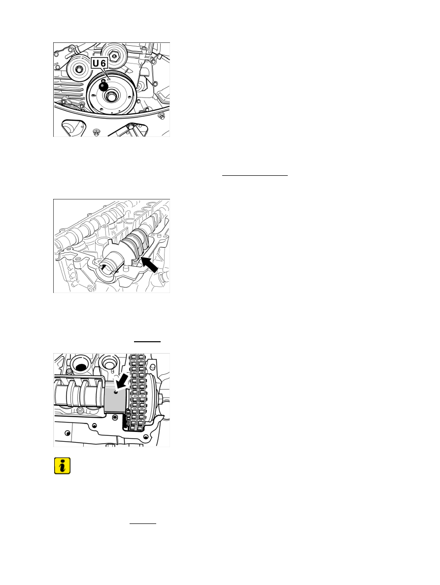
Pulley fixed at 60° before TDC

23. Turn the crankshaft by means of the pulley or vibration balancer clockwise (running direction of

engine

 further still until the marking U6 on pulley or vibration balancer coincides with fixing

bore in crankcase

 (60° before TDC). Fix with locating pin 9595/1.

24. Oil the bearing surfaces of the camshafts with new engine oil.

Inlet camshaft 1-3 in overlap

25. Insert inlet camshaft 1 - 3. Pull the control chain out of the chain housing of the cylinder head with a

welding wire and position on the toothed ring of the camshaft adjuster. Then insert the camshaft at
overlapping TDC of cylinder 1 (the cams of cylinder 1 point diagonally downwards towards the outside
of the cylinder head -arrow- ).

Position of bearing sleeve for inlet camshaft

Note

Make sure that the bearing sleeve on the inlet camshaft is positioned correctly.

• 

26. The bearing sleeve of the inlet camshaft must be positioned so that the centrally bored blind hole points

vertically upwards -arrow- (the rib of the cylinder head should also be at the centre in relation to the
bearing sleeve). In this position, the dowel pin in the bearing bore of the cylinder head will fit precisely

Diagnostic system: reading out fault memory and activating systems

Installing camshafts, adjusting timing - engine removed

381

into the opposite off-centre blind hole bore. Any other bores are through-holes for guiding the oil.

Exhaust camshaft 1-3 in overlap

27. Insert exhaust camshaft 1 - 3. Lay the control chain on the flange for the chain sprocket, then insert the

camshaft at overlapping TDC of cylinder 1 (the cams of cylinder 1 point diagonally downwards towards
the outside of the cylinder head).

Exhaust sprocket 1 - 3 at 60° before TDC

28. Insert exhaust camshaft sprocket in the timing chain and position on camshaft flange. The four

threaded bores in the camshaft flange must be fully visible on the left at the slotted curves of the
sprocket -arrows-

 so that the Torx screws M6 x 12 can still be positioned to fasten the sprocket.

Exhaust sprocket 1 - 3, all screws fitted

Diagnostic system: reading out fault memory and activating systems

Installing camshafts, adjusting timing - engine removed

382

Installation position of housing

Note

Do not interchange the thrust bearings of the inlet and exhaust camshafts during assembly; observe
identification markings.

• 

29. Insert three thrust bearings and one housing -arrows- for the bearing sleeve of the camshafts together

with the guide rail for the timing chain.

Position of housing screws

30. Insert eight housing screws (Torx): six M6 x 35 -1- and two M6 x 40 -2- for camshaft bearing and guide

rail. Tighten screws evenly and just finger-tight.

Timing for side 1 - 3

Note

Position crankshaft above the pulley or vibration balancer before final adjustment of the timing to the
TDC marking.

• 

Note

Before final tightening (torque angle) of the central screw, the special tool adjusting gauge 9686
must be removed.

• 

31. Final timing adjustment for cylinder bank 1 - 3 is analogous to that for cylinder bank 4 - 6. ;

Diagnostic system: reading out fault memory and activating systems

Installing camshafts, adjusting timing - engine removed

383

Chain tensioner, cylinder 1 - 3

32. Fit chain tensioner for side 1 - 3 (hexagon a/f 32) before turning crankshaft to the TDC mark. Fit

chain tensioner with new sealing ring and tighten. → Tightening torque: 59 ftlb.

After adjusting the timing, this should be re-checked.

Slot position of camshafts at overlap

33. Turn the engine 360° at the crankshaft and fix at the TDC mark. Check camshaft position of

cylinder bank 4 - 6 using the adjusting gauge 9686. Then turn a further 360° and check the
camshaft position of cylinder bank 1 - 3.

Subsequent work for installing camshafts

Subsequent work for installing camshafts

Diagnostic system: reading out fault memory and activating systems

 Subsequent work for installing camshafts

384


Content   ..  54  55  56  57   ..