Snowmobile Ski Doo REV SERIES (2004 year). Manual - part 45


  Index      Snowmobiles / ATV     Snowmobile Ski Doo REV SERIES - service manual 2004 year


Search            


Content   ..  43  44  45  46   ..


Snowmobile Ski Doo REV SERIES (2004 year). Manual - part 45


Section 05 2–TEC ENGINE MANAGEMENT
Subsection 01 (OVERVIEW)

OPERATING PRINCIPLE

For this SDI 2-stroke engine, a highly advanced en-
gine management system (EMS) has been used to
ensure a high power output combined with clean-
est combustion. An ECM (Engine Control Mod-
ule) calculates the proper air/fuel mixture and igni-
tion timing for each cylinder separately. The fuel
is injected into the transfer port of each cylinder.

AIR INDUCTION

Through air filter mounted LH side panel, air goes
into air silencer. The ECM measures at this point
air pressure and temperature. Then, air for com-
bustion is drawn through two throttle bodies. The
air flow is controlled by two throttle plates. The air
continues through the reed valves into the cylinder
base then the crankcase.

1

A32C8PA

THROTTLE BODY ASSEMBLY
1. Coolant-heated line

FUEL DELIVERY SYSTEM

GENERAL

When the piston reaches the correct position,
the ECM opens the fuel injectors and fuel is dis-
charged into the transfer ports of cylinders. This
air/fuel mixture is then ignited by the spark plug.

COMPONENT DESCRIPTION

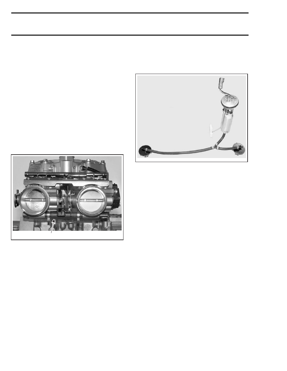
Fuel Pump and Fuel Pressure Regulator

They provide fuel pressure and flow rate to the
system.

The fuel pump module is located inside the fuel
tank. The module includes the fuel pump, the fuel
pressure regulator and the fuel level sensor (if so
equipped).

A33I06A

The fuel pressure regulator controls the pressure
in the system and allows the excess of fuel to
return to the fuel tank. The fuel pressure regulator
regulates the fuel pressure at 400 kPa (58 PSI).

Fuel Rail

The fuel rail is a small tube on which the four in-
jectors are mounted. It ensures at all times that
enough fuel at the right pressure can be delivered
to the fuel injectors. The fuel rail is fed by the fuel
pump module.

Fuel Injectors

Fuel injectors (two per cylinder) are used to inject
fuel into the transfer port of cylinder.

Throttle Body

It is a dual throttle body mounted on the engine in-
take side. Fitted on this dual throttle body, there
is a TPS (Throttle Position Sensor) that sends in-
formation to the ECM.

Fuel Pickups

The two fuel pickups come with 70 micron filter.
One is located at the front right side of the fuel
tank and the other at the rear left side.

166

mmr2004-Rev

Section 05 2–TEC ENGINE MANAGEMENT

Subsection 01 (OVERVIEW)

2

A33I07A

1

1. Fuel tank
2. Fuel pickups

In-Line Fuel Filter

The in-line 10 micron fuel filter is fastened under
the steering console. It comes as a complete as-
sembly.

A33I08A

ENGINE MANAGEMENT
SYSTEM (EMS)

The EMS

(Engine Management System)

is

equipped with an ECM which controls the ig-
nition system, the vehicle electrical system, the
fuel injection system and the electronically con-
trolled RAVE.

A32E3AA

TYPICAL — ECM

The ECM is mounted in the front of the vehicle.

A33I09A

The ECM is directly powered by the battery. It
is responsible for the following engine manage-
ment/electrical functions:

– interpreting information
– distributing information
– start/stop function
– DESS (Digitally Encoded Security System)
– ignition control
– injection control

NOTE: The ECM applies the proper maps (injec-
tion and ignition) for optimum engine operation in
all conditions.

– engine RPM limiter

mmr2004-Rev

167

Section 05 2–TEC ENGINE MANAGEMENT
Subsection 01 (OVERVIEW)

– RER (Rotax Electronic Reverse)
– etc.

The ECM features a permanent memory that will
keep the programmed tether cord cap(s) code,
fault codes and other vehicle information, even
when the battery is removed from the vehicle.

EMS — GENERAL FUNCTIONS

Automatic Power Shut-Down

The ECM is equipped with an automatic power
shut-down.

This feature prevents the battery

from losing its charge if the tether cord cap is
left on the post when the engine is not running
for more then 30 seconds. The ECM will remain
offline until the electric starter or the rewind
starter is activated. The ECM will shut down all
outputs after 5 seconds when the tether cord cap
is removed.

Antidrive Feature

This system allows the engine to reach pulley en-
gagement speed only if a programmed tether cord
cap is installed on DESS post. See below for de-
tails.

Digitally Encoded Security
System (DESS)

The following components are specially designed
for this system: ECM, tether cord cap and DESS
post.

The tether cord cap contains a magnet and a ROM
chip. The magnet actually closes the reed switch
inside the post which is the equivalent of a me-
chanical ON/OFF switch. The chip has a unique
digital code.

NOTE: Actually, it is the memory of the ECM
which is programmed to recognize the digital
code of the tether cord cap. This is achieved
with the VCK (Vehicle Communication Kit P/N 529
035 981). Refer to their operation manual or help
system to program a tether cord cap.

The system is quite flexible. Up to 8 tether cord
caps may be programmed in the memory of the
vehicle ECM. They can also be erased individually.

NOTE: If desired, a tether cord cap can be used
on other vehicle equipped with the DESS. It only
needs to be programmed for that vehicle.

When starting the engine with a tether cord cap
on the post, the DESS is activated and will emit
audible signals:

– 2 short beeps indicate a working tether cord

cap. Vehicle can be driven.

– 1 short beep indicates a wrong tether cord cap

is being used or that something is defective.
Vehicle can not be driven.

The memory of the ECM features two self-diag-
nostic modes for the DESS operation. Refer to
DIAGNOSTIC PROCEDURES section for more in-
formation.

The memory of the ECM is permanent. If the bat-
tery is disconnected, no information is lost.

Note that the DESS anti-drive circuitry is already
activated on all new ECMs.

Gauges Current Supply

The purpose of this function is to allow reading
of gauges without the engine running. It will give
access to most functions of the information center
gauge without starting the engine.

Gauges are supplied with current for 30 seconds
when connecting the tether cord cap on its post
and pressing the START/RER switch.

NOTE: Each time the tether cord cap is connected
to the post and START/RER switch is depressed,
the fuel pump is activated for 2 seconds to build
up pressure in the fuel injection system.

Engine Starting

If the ECM recognizes a valid tether cord cap, it
allows engine to rev above 3000 RPM.

If the tether cord cap is left on the DESS post for
more than 30 seconds after stopping the engine,
the ECM will shut down. The current supply to
gauges will be stopped as explained in the AN-
TIDRIVE FEATURE section.

Engine RPM Limiter

The ECM will limit the maximum engine speed.

Low-Oil Level Warning Device

When the oil falls under a certain level, the low oil
level LED will be illuminated. The buzzer will also
be activated intermittently.

168

mmr2004-Rev

Section 05 2–TEC ENGINE MANAGEMENT

Subsection 01 (OVERVIEW)

High Coolant Temperature
Warning Device

When the coolant temperature is getting to high,
the ECM sends out signals to the buzzer and the
high temperature LED.

Power Distribution

The ECM distributes power from battery to all ac-
cessories. Accessories are protected by fuses lo-
cated in the fuse holder. Fuses are identified be-
sides their holder.

IMPORTANT: The sensors and injectors are con-
tinuously powered with the supply from the bat-
tery. The ECM switches the ground to com-
plete the electrical circuits it controls. Take this
into account when troubleshooting the electrical
system.

Electric Start SDI Models

The system uses 2 relays: an ignition relay (R1)
and a headlights and accessories relay (R2).

Manual Start SDI Models

The system uses 3 relays: an ignition relay (R1),
a second for the headlights and the accessories
(R2) and a third for the capacitor circuit (R4).

ECU — ENGINE MANAGEMENT FUNCTIONS

A32A1SS

ENGINE

CONTROL

MODULE

(ECM)

Throttle position sensor (TPS)

Knock sensor (KS)

Exhaust gas temperature sensor (EGTS)

Crankshaft position sensor (CPS)

Buzzer

Ignition coil

RAVE solenoid

Fuel injector (4)

Fuel pump

Speedometer

Communication port

INPUTS

OUTPUTS

SDI SYSTEM

Air temperature sensor (ATS)

Air pressure sensor (APS)

Water temperature sensor (WTS)

Battery voltage

Digitally encoded security system (DESS)

START/RER button

Oil tank low-level

Communication port

mmr2004-Rev

169


Content   ..  43  44  45  46   ..