Snowmobile Arctic Cat (2008 year). Manual - part 158
8-35
8
INSPECTING
NOTE: Whenever a part is worn excessively,
cracked, or damaged in any way, replacement is
necessary.
1. Inspect the arm welded areas for cracks or any
signs of deterioration.
2. Inspect the bearings and axles for wear or dam-
age.
3. Inspect the arm tubing for signs of twisting or
bending.
INSTALLING UPPER ARMS
1. With the axles properly installed as noted during
removing, install the upper arms to the chassis;
then secure the arms with the cap screws and lock
nuts. Tighten to 32 ft-lb.
2. With the axle installed in the spindle, secure the
upper arms to the spindle with the cap screw and
lock nut. Tighten to 32 ft-lb.
REMOVING LOWER A-ARM
NOTE: To remove the lower A-arms, it will be
necessary to remove the air silencer. Proceed to
Air-Intake Silencer (Liquid-Cooled F-Series/T-
Series Models) sub-section in Section 4 and follow
REMOVING procedure.
1. Elevate the front of the snowmobile with a suitable
safety stand or lift.
2. Remove the cap screw and lock nut securing the
shock absorber to the spindle; then remove the
shock from the spindle and account for the shock
sleeve.
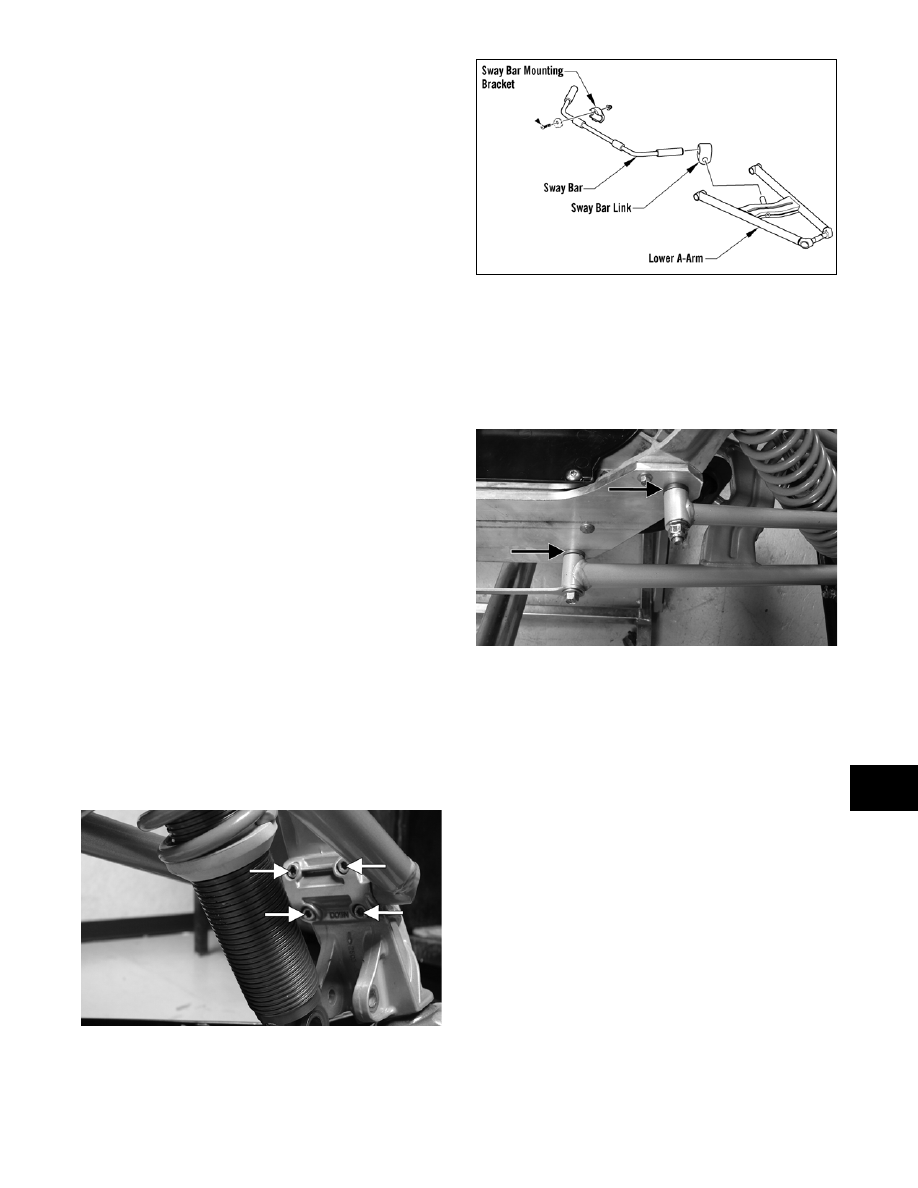
3. Remove the four torx-head cap screws securing
the lower A-arm bearing cap to the spindle; then
remove the cap and lower arm from the spindle.
ZJ174A
4. Secure the upper arms and spindle out of the way;
then remove the sway bar/link from the lower arm.
0742-219
5. Remove the cap screws and lock nuts securing the
lower A-arm to the chassis; then remove the arm
from the sway bar and chassis and account for the
axles.
NOTE: For installing purposes, note the posi-
tion of the axle shoulders.
ZJ168A
6. If applicable using a flat-blade screwdriver, pry
the split bearings from the spindle axle of the A-
arm.
NOTE: The split bearings cannot be reused;
they must be replaced with new ones.
INSPECTING
NOTE: Whenever a part is worn excessively,
cracked, or damaged in any way, replacement is
necessary.
1. Inspect the arm welded areas for cracks or any
signs of deterioration.
2. Inspect the bearings and axles for wear or dam-
age.
3. Inspect the arm tubing for signs of twisting or
bending.