Snowmobile Arctic Cat (2008 year). Manual - part 149
7-156
FS016
22. Install the button-head screw into the nitrogen
valve.
FS040
23. Clean all oil residue from the shock and reservoir
with solvent and dry with compressed air in a well
ventilated area.
24. Install the polyurethane bushings and steel sleeves
into the eyelets.
Shaft Eyelet
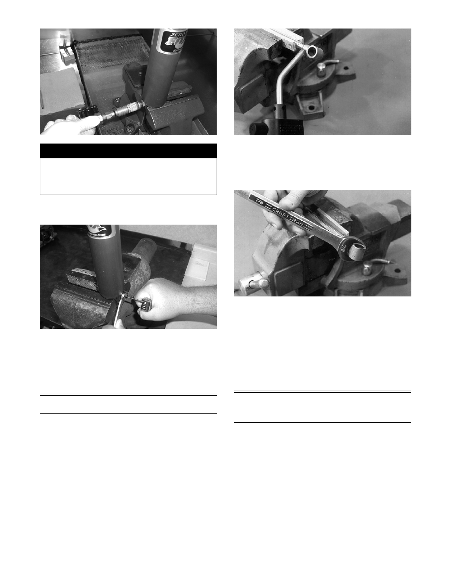
REMOVING
1. Using Shock Rod Clamping Tool to prevent dam-
age to the shaft surface, place the shock shaft into
a vise.
2. Heat the shaft eyelet with a torch to soften the
Loctite.
AG260
NOTE: The eyelet must be heated up to 300° for
the Loctite to soften.
3. Using a wrench, unscrew the eyelet from the shaft.
AG261
NOTE: With the eyelet removed, inspect the bot-
tom-out bumper for cracks or wear.
INSTALLING
1. Clean shaft threads and eyelet threads.
2. Apply red Loctite #271 to both threads, install the
eyelet, and tighten securely.
Pressurizing
Rebuildable Shocks
To pressurize the gas shock absorber, a regulator sys-
tem and a nitrogen tank will be needed.
! WARNING
Charge the shock using nitrogen gas only. DO NOT
CHARGE WITH ANY OTHER TYPE OF GAS. Doing so
will compromise the performance of the shock and
may be EXTREMELY DANGEROUS.