Snowmobile Arctic Cat (2008 year). Manual - part 140


  Index      Snowmobiles / ATV     Snowmobile Arctic Cat - service manual 2008 year


Search            


Content   ..  138  139  140  141   ..


Snowmobile Arctic Cat (2008 year). Manual - part 140


7-120

TZ017A

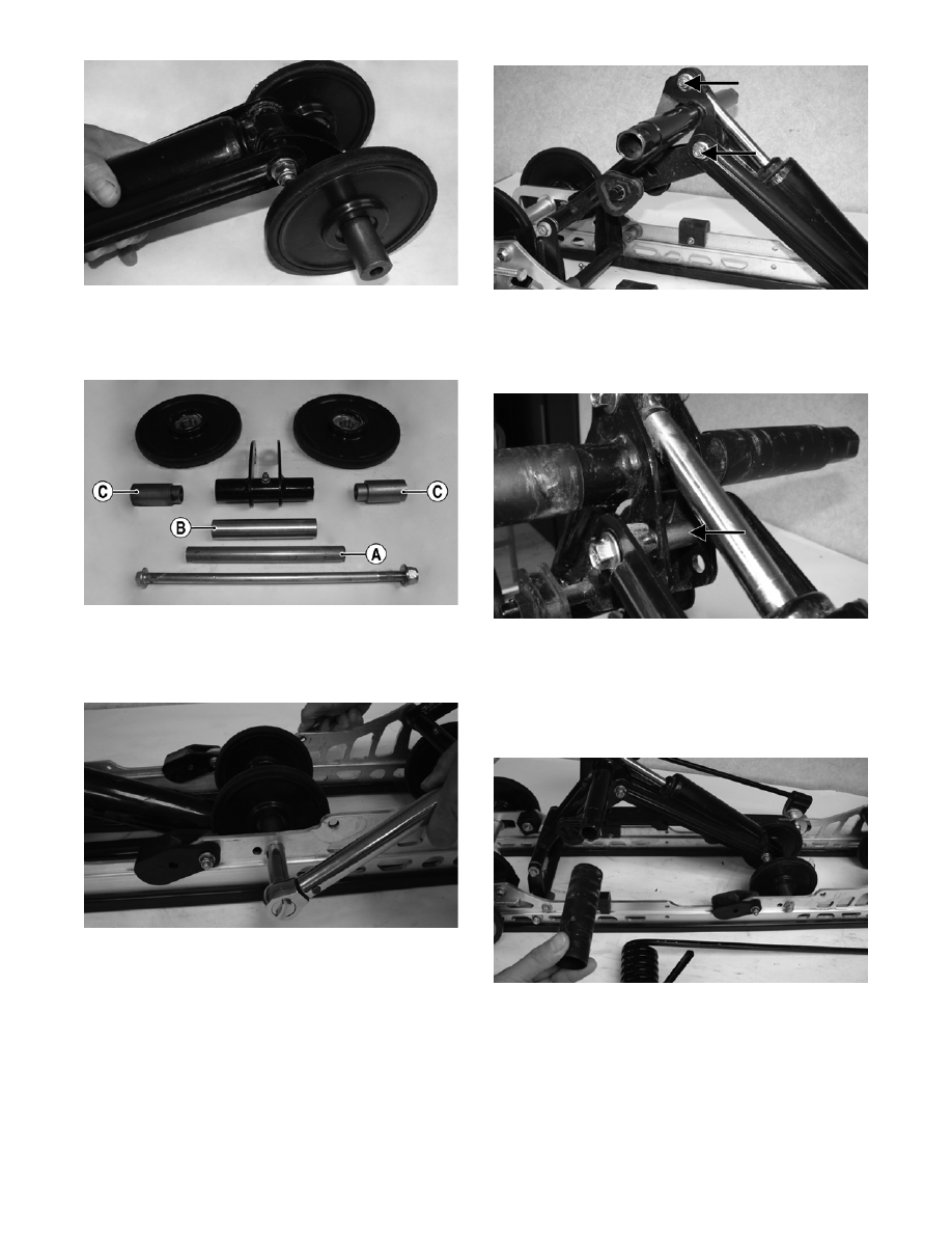
4. Assemble the rear shock pivot idler wheel assem-

bly with the axle (A), axle tube (B), axle spacers

(C), and shim washers (if applicable).

TZ014A

5. Install the rear shock pivot/idler wheel assembly to

the mounting location in the slide rails and secure

with cap screws and lock nuts.  Tighten to 20 ft-lb.

TZ019

6. With the sleeves installed, install the shock

absorber to the mounting hole of the idler arm

along with the cap screw and lock nut; then secure

the shock absorber links and spacer to the upper

mounting hole of the idler arm with cap screws

and lock nuts. Tighten securely.

TZ010B

„NOTE: Do not over-tighten the shock absorber
cap screw as the shock eyelet must be free to
pivot.

TZ020A

„NOTE: Be sure that the spacer is installed
between the brackets of the idler arm before secur-
ing the shock links.

7. Slide the sleeve and spring onto the idler arm.

TZ009

8. Place the spring slide and slide block (with spring

in slide block) into position on the slide rail.

Secure with a cap screw and washer. Tighten to 20

ft-lb.

7-121

7

TZ008

„NOTE: It is advisable to install the rear arm
springs onto the adjuster blocks after the skid
frame has been installed.

TZ021

9. With a suitable driving tool, install the rear upper

idler wheel on the idler arm.

TZ022

MS072A

10. Install the idler spacer collar onto the idler arm.

TZ023

11. Install the axle with a thin flat washer through the

back side of the flared bushing of the pivot arm.

„NOTE: If the flared bushing in the pivot arm is
loose, it must be cleaned and green Loctite #609
must be applied to it prior to installation.

12. Align the marks on the idler arm to the centerline

of the pivot arm assembly. Secure the pivot arm to

the idler arm with cap screws and lock nuts.

Tighten to 18 ft-lb.

TZ004B

„NOTE: When tightening the pivot arm lock nuts,
tighten the lower lock nut first or binding may
occur. Make sure the flared side of the bushing is
directed outward.

! CAUTION

When driving the idler wheel onto the idler arm, use
a tool to contact the inside race of the bearing or
damage to the wheel or bearing may occur.

7-122

TZ004C

13. Grease the idler arm and rear arm grease fittings

with a low-temperature grease.

Rear Axle and Slide Rail 

Idler Wheels

DISASSEMBLING REAR AXLE

„NOTE: The skid frame must be removed for this
procedure (see Removing Skid Frame in this sub-
section).

0742-937

1. Remove the cap screw and large flat washer secur-

ing the outer rear idler wheel. Remove the outer

idler wheel from the shaft.

2. Loosen the track adjusting bolts. Slide the outer

adjuster bushings off the axle.

3. Carefully slide the shaft out from the slide rails

and inner idler wheels. Account for the rear idler

wheel spacer and adjuster bushings.

REMOVING SLIDE RAIL IDLER 
WHEELS

„NOTE: The skid frame does not have to be
removed for this procedure.

1. Remove the cap screw and lock nut securing the

idler wheel to the idler wheel mounting block;

then remove the cap screw and lock nut securing

the mounting block to the slide rail.

TZ024A

MS003A

2. Account for a flat washer from the idler wheel cap

screw.

CLEANING AND INSPECTING

„NOTE: Whenever a part is worn excessively,
cracked, or damaged in any way, replacement is
necessary.

1. Clean the bearing with a clean cloth.

2. Inspect each idler wheel for cracks or damage.

3. Rotate the idler wheel bearing (by hand) and

inspect for binding or roughness.

4. If a bearing must be replaced, use this procedure.

A. Remove the bearing snap ring.

B. Using a suitable press or suitable driving tool,

remove the bearing from the inside of the

wheel.

C. Press the new bearing (on its outer race) into

the idler wheel.

! CAUTION

Do not remove the bearing unless it is absolutely
necessary. The bearing will be damaged during
removal.

7-123

7

MS006A

D. Install the snap ring making sure the “sharp

side” is directed away from the bearing.

MS007A

INSTALLING SLIDE RAIL IDLER 
WHEELS

1. Secure the mounting block on the slide rail with a

cap screw and lock nut. Tighten to 20 ft-lb.

„NOTE: For proper alignment, it is advisable to
install an idler wheel cap screw into the top mount-
ing block hole prior to tightening.

TZ025

2. Place the idler wheel to the mounting block; then

secure the idler wheel assembly with a cap screw,

flat washer, and a lock nut. Tighten to 20 ft-lb.

TZ026

ASSEMBLING REAR AXLE

742-937A

1. In order from the right-hand side, slide the axle

through the slide rail axle slot; then place a bush-

ing (A), inner idler wheel (B), and long spacer (C)

with a flat washer on the axle. Slide the axle

through the opposite slide rail axle slot.

2. Place the plastic adjuster bushings (D) on the axle

(on the outside of each axle slot); then install the

outer idler wheels on the axle and secure with two

cap screws (E) (coated with blue Loctite #243) and

large flat washers. Tighten cap screws only until

snug.

„NOTE: Care must be taken that the adjuster
bushing slot with the cap screw hole is aligned
properly with the adjuster bolt.

MS058A


Content   ..  138  139  140  141   ..