Snowmobile Arctic Cat (2008 year). Manual - part 60


  Index      Snowmobiles / ATV     Snowmobile Arctic Cat - service manual 2008 year


Search            


Content   ..  58  59  60  61   ..


Snowmobile Arctic Cat (2008 year). Manual - part 60


2-178

„NOTE: For assembling purposes, it is advisable
to lubricate the rubber side of the washer before
installing.

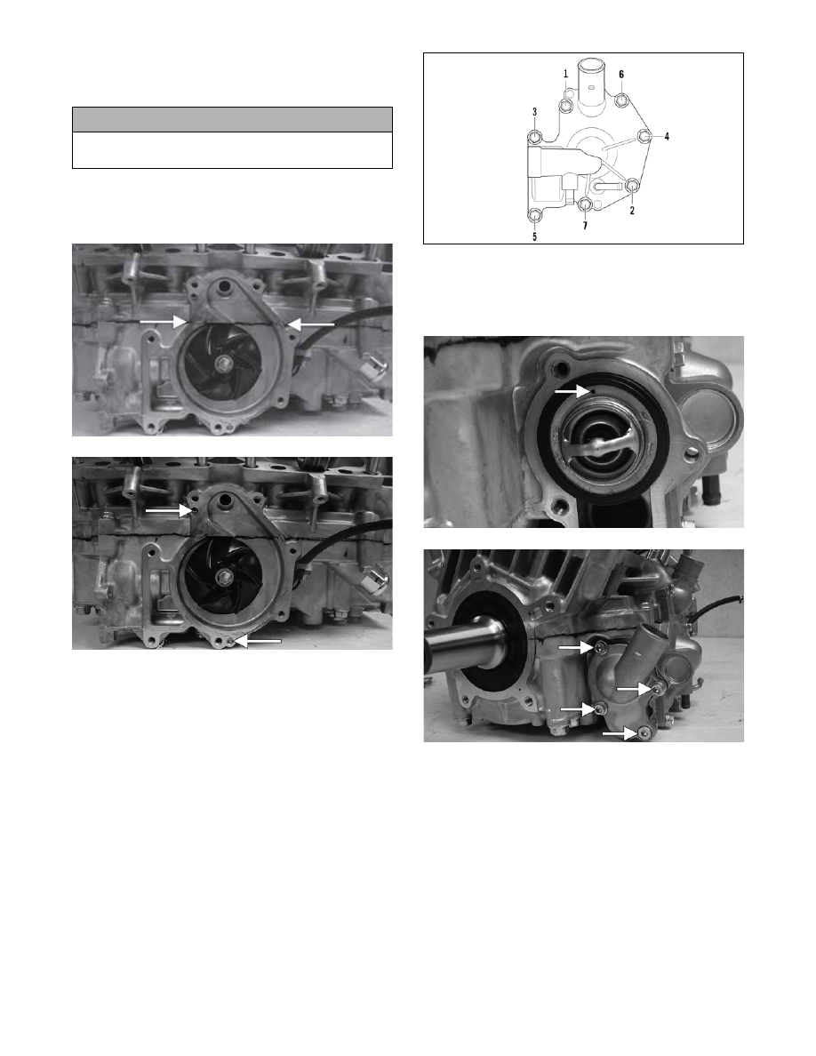
25. Apply high-temperature sealant to the crankcase/

water pump cover seam; then install the dowel

pins into the crankcase.

CM171A

CM171B

„NOTE: Sealant is only required on the crankcase
seam.

26. Apply a thin film of low-temp grease to the water

pump cover O-ring; then position the O-ring into

the water pump cover. With the alignment pins in

place, install the cover. Secure with seven screws

using the pattern shown. Tighten to 8 ft-lb.

0742-257

27. With the bypass valve of the thermostat directed to

the 12 o’clock position, install the thermostat and

housing; then in a crisscross pattern, tighten the

cap screws to 8 ft-lb.

CM157A

CM155A

28. Place the cylinder base gasket into position on the

crankcase.

29. Install the piston rings on each piston so the letter

on the top (inclined surface) of each ring faces the

dome of the piston.

! CAUTION

If the rubber side of the washer is not positioned
toward the impeller, a coolant leak will result.

2-179

2

726-306A

30. Apply oil to the connecting-rod small end bear-

ings; then install the small-end bearings. Install a

washer on each side of the connecting rod.

„NOTE: The shoulder side of the washer must
seat to the needle bearing.

CM172A

31. Place each piston over the connecting rod so the

indicator dot on each piston will point toward the

intake/exhaust ports; then secure with an oiled pis-

ton pin.

„NOTE: The indicator dot is found on the piston
dome.

CM173

32. Install the new circlips so the open end is directed

either up or down.

CM174

33. Rotate each piston ring until the ring ends are

properly positioned on either side of the ring

keeper; then apply oil to the piston assemblies and

cylinder bores. Remove the rubber hoses from the

connecting rods.

34. In turn on each cylinder, place a piston holder (or

suitable substitute) beneath the piston skirt and

square the piston in respect to the crankcase; then

using a ring compressor or the fingers, compress

the rings and slide the cylinder over the piston.

Remove the piston holder and seat the cylinder

firmly onto the crankcase.

„NOTE: The cylinders should slide on easily. DO
NOT force the pistons into the cylinders.

CM148

35. Secure each cylinder by installing the four nuts

and four new cap screws. DO NOT TIGHTEN AT

THIS TIME.

„NOTE: Always use new cap screws when install-
ing the cylinders.

36. Secure the cylinders (from step 35) by tightening

the cylinder base nuts and cap screws to 42 ft-lb in

three steps using the appropriate pattern shown.

! CAUTION

Incorrect installation of the piston rings will result in
engine damage.

! CAUTION

Make sure the circlips are firmly seated and the open
end is directed either up or down before continuing
with assembly.

2-180

0738-206

0738-220

37. Install the two cylinder O-rings on the top of each

cylinder making sure they are correctly positioned

in the grooves.

FC077

„NOTE: Lubricating the O-rings with a light coat of
grease will help keep them seated in the grooves
of the cylinder.

38. Place new O-rings onto each of the head cap

screws. Place four of these cap screws (from oppo-

site end of each other) into the cylinder head.

Thread the spark plugs in part way; then while

holding the head above the cylinder, carefully start

and finger-tighten all four cap screws while

observing the cylinder O-rings to make sure they

remain in position. Slowly place the head into

position on top of the O-rings.

CM175

„NOTE: On the 800 cc to install the remaining cap
screws, the spark plugs must be removed.

39. Start and finger-tighten the remaining cap screws

being very careful not to move the cylinder head;

then tighten the cap screws in two steps to 25 ft-lb

using the appropriate pattern shown.

0742-200

0742-199

„NOTE: At this point on the 800 cc, install the
spark plugs; then on both models, tighten the
spark plugs to 19 ft-lb.

„NOTE: At this point on the 800 cc, install the
knock sensor with the lock plate, tighten the sen-
sor securely, and bend the lock plate tabs up.

800 cc

1000 cc

800 cc

1000 cc

2-181

2

40. With the APV gaskets properly positioned as

noted during disassembly and with the raised edge

of the valve aligned with the channel of the cylin-

der, slide the APV assemblies into position in the

cylinders; then secure with cap screws (coated

with blue Loctite #243). Tighten to 8 ft-lb.

CM204

„NOTE: At this point, pressure test the engine
(see Section 3).

41. Secure the stator plate to the crankcase with the

Allen-head cap screws (coated with blue Loctite

#243) and tightened to 8 ft-lb.

42. Route the stator harness through the opening in the

crankcase; then secure the stator to the stator plate

with the Allen-head cap screws (coated with blue

Loctite #243). Tighten to 8 ft-lb.

CM143A

43. Secure the upper ignition timing sensor with cap

screws (coated with blue Loctite #243). Tighten

securely; then install the wiring grommet into the

notch of the crankcase.

CM176A

44. Secure the lower ignition timing sensor with two

cap screws (A) (coated with blue Loctite #243).

Tighten securely; then install the grommet. With

the stator harness properly positioned, install the

plate and cap screw (B) (coated with blue Loctite

#243). Tighten securely.

CM177A

45. Install the key in the crankshaft. 

46. Place the starter pulley in position on the flywheel;

then loosely secure the starter pulley with three

cap screws (coated with blue Loctite #243). While

holding the starter pulley, slide the flywheel onto

the crankshaft making sure the keyways match.

CM180

„NOTE: Before installing the flywheel, be sure to
wipe the crankshaft and flywheel tapers clean
using a clean towel.


Content   ..  58  59  60  61   ..