Snowmobile Arctic Cat (2008 year). Manual - part 54


  Index      Snowmobiles / ATV     Snowmobile Arctic Cat - service manual 2008 year


Search            


Content   ..  52  53  54  55   ..


Snowmobile Arctic Cat (2008 year). Manual - part 54


2-154

CM184B

13. With the flange clamps in place, install the throttle

body assembly and connect the oil pump cable/

control rod; then connect the throttle body coolant

hose to the PTO-side throttle body and secure with

the clamp.

CM028A

FS198A

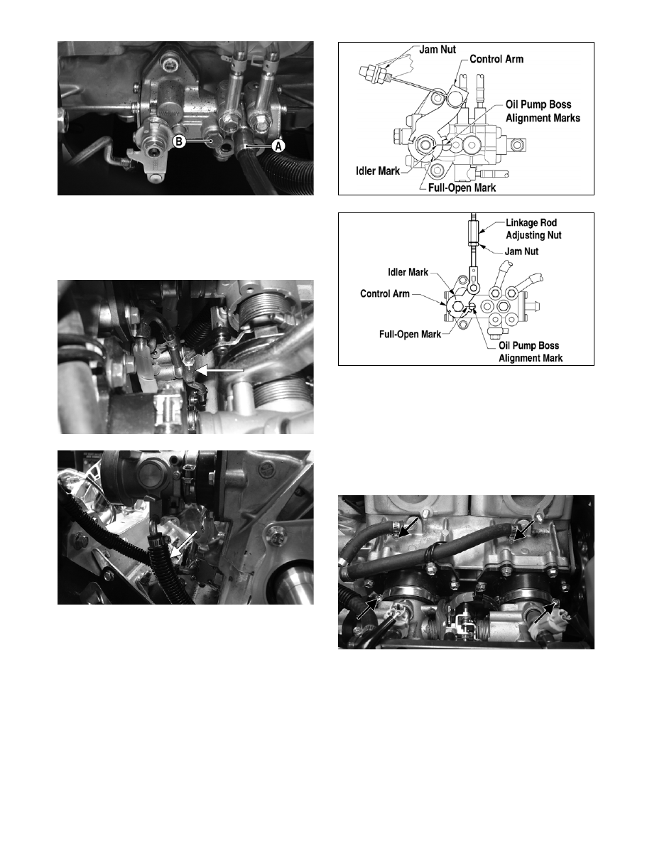
„NOTE: Check to be sure the mark on the control
arm is aligned with alignment mark on the oil-
injection pump boss in the full-open position. If the
marks are not aligned, adjust synchronization by
loosening the jam nuts on the adjuster. Rotate the
jam nuts/adjuster nut until proper alignment is
attained. Tighten jam nuts.

0742-853

0742-854

„ NOTE: On the 500 cc when the cable adjusting
nut is adjusted correctly, the throttle lever will
move approximately 1/8 in. before the oil-injection
pump control arm begins to move.

14. Install the two coolant hoses to the MAG-side and

PTO-side of the crankcase (below the exhaust

ports); then tighten the coolant hose clamps and

the carburetor flange clamps.

FS271A

15. Apply a thin coat of high-temperature silicone

sealant to each exhaust port; then install the

exhaust gaskets.

16. Apply a thin coat of high-temperature silicone

sealant to the mating surfaces of the exhaust mani-

fold; then install the exhaust manifold and secure

with six nuts. Tighten the nuts to 15 ft-lb.

500 cc

600 cc

2-155

2

FS272

17. Route the gasline hose to the throttle body assem-

bly and secure the hose to the fuel rail. Tighten the

clamp securely; then using a cable tie, secure the

hose to the MAG-side engine mounting bracket.

18. Connect the coolant overflow hose to the cylinder

head; then connect the spark plug wires to the

spark plugs.

„NOTE: Steps 19-21 are for the 600 cc engine.

19. Rotate the servomotor clockwise to remove any

slack from the cables.

20. Slide the APV cable drums into the servomotor

actuator; then place the cable housings into posi-

tion in the servomotor. Secure the APV cables

with the cable holder.

FS176

21. Check APV cable adjustment. See Arctic Power

Valve (APV) System in Section 3.

„NOTE: Before installing the drive clutch, be sure
to wipe both the crankshaft taper and clutch
mounting taper clean using a clean towel.

22. Place the drive clutch into position on the crank-

shaft and secure with the cap screw and lock

washer. Tighten to 55 ft-lb.

23. Install the alignment washers (if applicable); then

install the driven pulley on the gear case input

shaft. Tighten the cap screw to 32 ft-lb.

FS192

24. Check drive clutch/driven pulley alignment (see

Section 6). Install the drive belt. Check belt deflec-

tion. Secure the belt guard (see Section 6).

25. Secure the bearing bracket/steering post assembly

to the upper support plate with the bracket plates

and cap screws (coated with blue Loctite #243).

Tighten the cap screws to 8 ft-lb.

FS182A

„NOTE: When installing the bracket plates, the
wider end of the plate must be directed up.

! CAUTION

When installing the throttle bodies, make sure the
gasline hose is properly routed to avoid premature
wear and/or contact with exhaust components.

! CAUTION

When installing the drive clutch, do not tighten the
clutch cap screw with any kind of impact tool.
Tighten cap screw using a hand torque wrench only.
Failure to do so could result in stationary sheave
damage.

2-156

FS200A

26. Install the air silencer onto the throttle bodies mak-

ing sure the dual intake boot is properly positioned

and seated.

„NOTE: To aid in installing the air silencer, it can
be helpful to remove the air silencer cover and
work the intake boot over the throttle body from
inside the silencer.

FS201A

27. Place the front bumper assembly (with spar pan-

els) into position on the snowmobile; then secure

the front and rear spar panels together with the

torx-head cap screws and lock nuts (A). Tighten

the lock nuts securely.

742-207A

28. Install the body screws and lock nuts (C) from

each side and the self-tapping screws (B) from

each side securing the front bumper assembly to

the chassis. Tighten all hardware securely.

29. Connect the air temperature sensor and place the

sensor harness beneath the air-intake duct; then

install the duct into the silencer.

„NOTE: To aid in installing the duct, it can be help-
ful to apply a thin film of WD-40 to the air silencer
seal and to work the duct back and forth until the
sleeve of the duct is properly seated into the
silencer.

30. Secure the air-intake duct to the upper frame with

the cap screw. Tighten securely.

„NOTE: If the ECU was removed to gain access to
the air-intake duct cap screw, install the ECU using
the two lock nuts. Tighten the lock nuts securely;
then connect the harness plug-ins to the ECU.

FS202A

31. Using the illustration following step 27, secure the

left-side rear spar panel to the gas tank and support

tube with the three torx-head screws (D). Tighten

the screws securely.

32. On the standard models, place the seat into posi-

tion on the chassis; then push down on the rear of

the seat until it locks securely in place.

„NOTE: On the LXR and Sno Pro models, install
the seat; then install the machine screw (threads
coated with blue Loctite #243) to the right side of
the seat support.

33. Fill the cooling system (see Liquid Cooling Sys-

tem in Section 3).

34. Place the rubber exhaust bumper into position on

the chassis.

! CAUTION

Make sure to place the sensor harness beneath the
air-intake duct to avoid contact with exhaust compo-
nents.

! CAUTION

It is critical that machine screw is not installed tight
against the seat support. The screw must be loose
enough to be effective as a seat “stop.”

2-157

2

FS203A

„NOTE: On the LXR, secure the negative battery
cable to the battery.

35. Install the exhaust resonator and secure to the

upper frame with the tab washer and the hairpin

clip.

36. Place gaskets on the resonator and exhaust mani-

fold; then install the expansion chamber. Secure

the chamber to manifold and upper frame with the

springs.

„NOTE: When installing the exhaust manifold
springs, the long hook portion of the spring must
be attached to the exhaust manifold or premature
spring failure will result.

37. Place the console into position on the headlight

support bracket (do not secure the console with the

torx-head screws at this time); then connect the

console/main harness plug-in.

38. Install and close the left-side and right-side access

panels and the hood.

39. Start the engine and warm up to operating temper-

ature; then verify that all components are function-

ing properly and that coolant is circulating through

the cooling system properly.

40. Allow the engine to cool; then check the coolant

level and add coolant as necessary.

41. Verify the tightening torque of the drive clutch.

42. Secure the console to the steering support with the

torx-head screws and tighten the screws securely;

then close the left-side and right-side access panels

and close the hood.

741-722A

Engine - 

F-Series 800/1000

This engine servicing sub-section has been organized

to show a progression for the complete servicing of the

Arctic Cat 800 cc/1000 cc (F-Series) engines. For con-

sistency purposes, this sub-section shows a complete

and thorough progression; however, for efficiency it

may be preferable to remove the engine as a complete

assembly, to remove and disassemble only those com-

ponents which need to be addressed, and to service

only those components. Also, some components may

vary from model to model. The technician should use

discretion and sound judgment.

„NOTE: Critical torque specifications can be
found in Section 1 of this manual.

„NOTE: Some illustrations and photographs used
in this section are used for clarity purposes only
and are not designed to depict actual conditions.

! CAUTION

Never run the engine with the console harness dis-
connected or damage to the electrical system will
result.

! CAUTION

After running the engine to the proper operating tem-
perature, shut the engine off; then open the hood
and access panels and inspect for any signs of cool-
ant, gasoline, or oil leakage.

! CAUTION

If the engine had a major overhaul or if any major
component was replaced, proper engine break-in
procedures must be followed (see Section 1). If the
proper engine break-in procedures are not followed,
severe engine damage may result.


Content   ..  52  53  54  55   ..