Snowmobile Arctic Cat (2008 year). Manual - part 37


  Index      Snowmobiles / ATV     Snowmobile Arctic Cat - service manual 2008 year


Search            


Content   ..  35  36  37  38   ..


Snowmobile Arctic Cat (2008 year). Manual - part 37


2-85

2

„NOTE: On the 500 cc after tightening the crank-
case, turn the engine right side up and tighten the
four MAG-housing cap screws in a crisscross pat-
tern to 16 ft-lb.

738-202A

„NOTE: On the 500 cc, secure the connecting rods
with rubber bands. On the 600 cc, secure the con-
necting rods with rubber hoses.

15. Install the oil-injection pump retainer O-ring and

retainer.

FC082

„NOTE: For assembling purposes, always use
new O-rings lubricated with oil on the oil injection
pump and retainer.

16. Install the O-ring and the oil-injection pump mak-

ing sure the pump shaft slot and pump driven gear

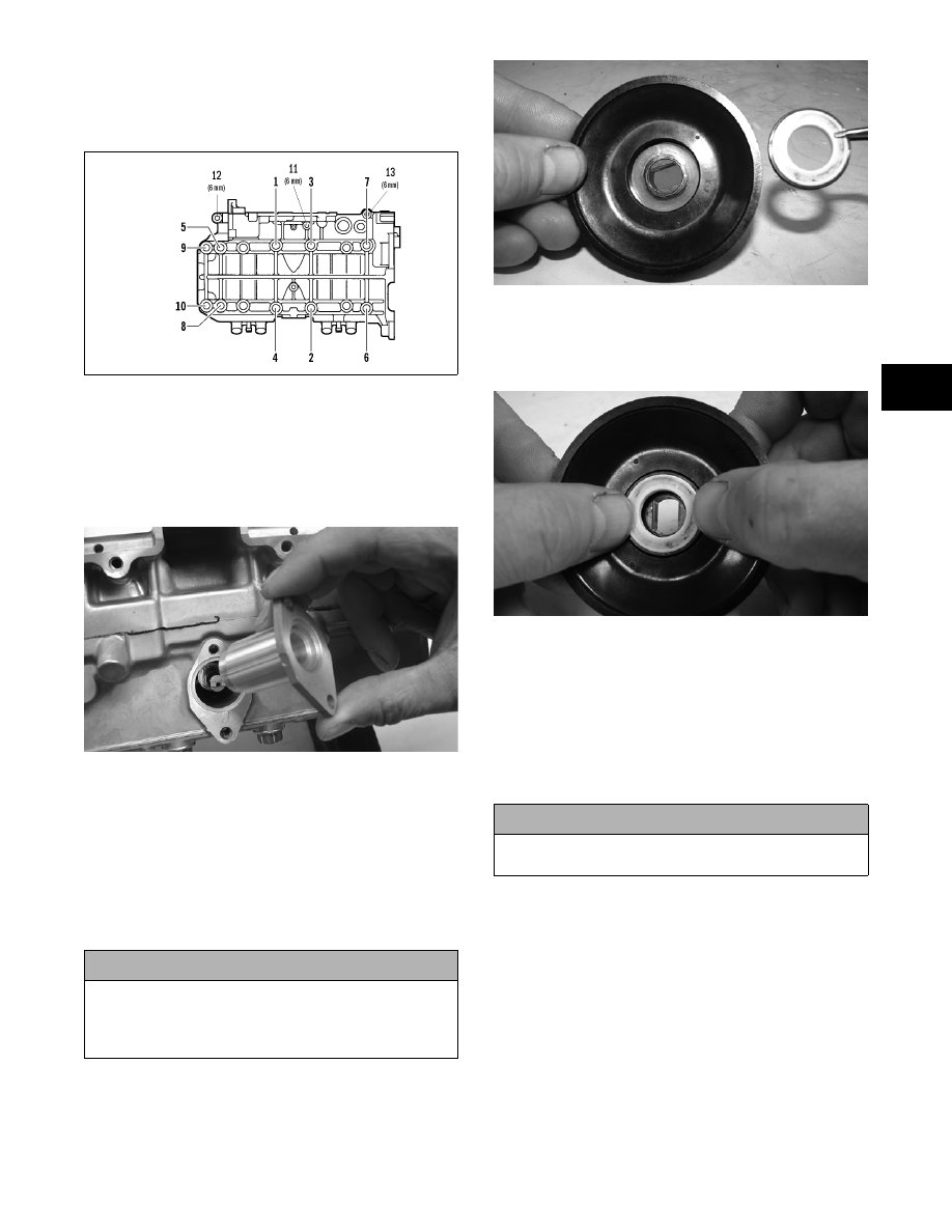
shaft align. Secure with two screws (coated with

blue Loctite #243). Tighten the two screws to 8 ft-

lb.

17. Position the ceramic/rubber seal into the back side

of the water pump impeller with the ceramic face

of the seal directed out.

CM168

18. Using both thumbs, press the seal into position

making sure its marked side is positioned towards

the rubber seal cup; then apply a thin coat of

grease to the seal outer surface.

CM169

19. Place the impeller into position and secure with a

cap screw and washer. Be sure the rubber side of

the washer is directed toward the impeller. Apply

blue Loctite #243 to the threads of the cap screw

and tighten to 8 ft-lb.

„NOTE: For assembling purposes, it is advisable
to lubricate the rubber side of the washer before
installing.

20. Apply high-temperature sealant to the crankcase/

water pump cover seam; then install the dowel

pins into the crankcase.

! CAUTION

Be sure the oil-injection pump/water pump drive-
shaft is properly aligned with the slot of the oil-injec-
tion pump. The pump will be damaged if these two
components are not aligned.

600 cc

! CAUTION

If the rubber side of the washer is not positioned
toward the impeller, a coolant leak will result.

2-86

FC133A

„NOTE: It is important to not get sealant into the
breather hole in the crankcase. If sealant gets into
the hole, carefully remove before proceeding.

FC072B

FC072A

„NOTE: Sealant is only required on the crankcase
seam.

21. Lubricate the O-ring with a light coat of grease;

then position the O-ring into the water pump

cover. Install the cover; then secure with six

screws. Tighten to 8 ft-lb.

FC134

22. Noting the alignment dots, install the thermostat

housing with thermostat. Tighten the existing

hardware to 8 ft-lb.

FC078A

FC073

23. Secure the intake flanges, reed valve assemblies,

and gaskets with cap screws. Tighten to 13 ft-lb in

a crisscross pattern.

24. Install the dowel pins into the crankcase; then

place the cylinder base gasket into position on the

crankcase.

25. Install the piston rings on each piston so the letter

on the top (inclined surface) of each ring faces the

dome of the piston.

2-87

2

726-306A

26. Apply oil to the connecting-rod small end bear-

ings; then install the small-end bearings. Install a

washer on each side of the connecting rod.

FC075

„NOTE: The shoulder side of the washer must
seat to the needle bearing.

27. Place each piston over the connecting rod so the

indicator dot on each piston will point toward the

intake/exhaust ports; then secure with an oiled pis-

ton pin.

„NOTE: The indicator dot is found on the piston
dome top.

FC079A

28. Install the new circlips so the open end is directed

either up or down.

„NOTE: To aid in the circlip installation, it is advis-
able to install the circlip to the inside of the piston
before installing the connecting rod.

B324D

29. Rotate each piston ring until the ring ends are

properly positioned on either side of the ring

keeper; then apply oil to the piston assemblies and

cylinder bores. Remove the rubber bands or hoses

from the connecting rods.

30. In turn on each cylinder, place a piston holder (or

suitable substitute) beneath the piston skirt and

square the piston in respect to the crankcase; then

using a ring compressor or the fingers, compress

the rings and slide the cylinder over the piston.

Remove the piston holder and seat the cylinder

firmly onto the crankcase.

„NOTE: The cylinders should slide on easily. DO
NOT force the cylinders on.

FC076

31. On the 500 cc, secure the cylinders by installing

the eight nuts. DO NOT TIGHTEN AT THIS

TIME.

! CAUTION

Incorrect installation of the piston rings will result in
engine damage.

! CAUTION

Make sure the circlips are firmly seated and the open
end is directed either up or down before continuing
with assembly.

2-88

32. On the 600 cc, secure the cylinders by installing

the four nuts and four cap screws. DO NOT

TIGHTEN AT THIS TIME.

33. Install the oil-injection hoses and secure with the

clamps; then place the lower check-valve assem-

bly into position and secure with the gaskets and

union cap screw. Tighten securely.

34. Secure the cylinders (from steps 31-32) by tighten-

ing the cylinder base nuts (and cap screws on the

600 cc) to 42 ft-lb in three steps using the appro-

priate pattern shown.

0742-746

0738-220

35. Install the two cylinder O-rings on the top of each

cylinder making sure they are correctly positioned

in the grooves.

FC077

36. Place new O-rings onto each of the head cap

screws. Place four of these cap screws into the cyl-

inder head. While holding the head above the cyl-

inder, carefully start and finger-tighten all four cap

screws while observing the cylinder O-rings to

make sure they remain in position. Slowly place

the head into position on top of the O-rings. Start

and finger-tighten the remaining cap screws being

very careful not to move the cylinder head.

37. From step 36 in two steps, tighten the 8 mm cap

screws to 19 ft-lb (500 cc) or 25 ft-lb (600 cc)

using the appropriate pattern shown.

0738-204

„NOTE: On the 500 cc after tightening the 8 mm
cap screws to 19 ft-lb, tighten the two remaining 6
mm cap screws to 8 ft-lb.

0738-205

38. On the 600 cc, route the APV cables between the

cylinders; then slide the APV assemblies into posi-

tion in the cylinders. Slide the valve keepers into

position and secure with cap screws. Tighten to 10

ft-lb.

500 cc

600 cc

! CAUTION

The long side of the exhaust valve must be facing
toward the cylinder head or severe engine damage
may occur.

500 cc

600 cc


Content   ..  35  36  37  38   ..