Snowmobile Arctic Cat (2008 year). Manual - part 34


  Index      Snowmobiles / ATV     Snowmobile Arctic Cat - service manual 2008 year


Search            


Content   ..  32  33  34  35   ..


Snowmobile Arctic Cat (2008 year). Manual - part 34


2-73

2

AN327D

Servicing Top-Side 

Components 

Many services can be performed without removing the

engine. Some components may vary from model to

model. The technician should use discretion and sound

judgment when removing and installing components.

„NOTE: Some photographs used in this sub-sec-
tion are used for clarity purposes only and are not
designed to depict actual conditions.

REMOVING TOP-SIDE 
COMPONENTS

To access top-side components, use the following pro-

cedure:

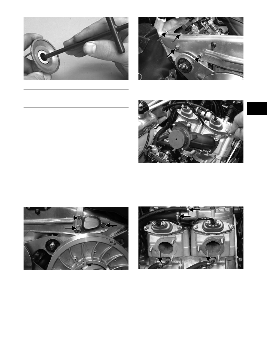
1. Remove the cap screws securing the left-side

steering support and the side-plate brace to the

chassis; then remove the brace.

CM211A

CM212A

2. Remove the expansion chamber and resonator;

then remove the exhaust manifold.

CM213

3. Drain the engine coolant (see Liquid Cooling Sys-

tem - Section 3).

4. Remove the coolant hose and breather hose con-

nected to the cylinder head; then disconnect the

two coolant hoses located beneath the exhaust

ports on the cylinders.

CM214A

5. On the 600 cc, disconnect the APV cables from

the servomotor; then remove the APV’s from the

cylinder.

2-74

CM215

6. Remove the twelve 10 mm cap screws and two 8 mm

cap screws (500 cc) securing the cylinder head; then

remove the cylinder head. Account for the O-rings.

CM216

„NOTE: Note that the APV exhaust valves and the
gaskets are directional for assembling purposes.

„NOTE: At this point, remove all loose hardware to
avoid any falling down into the chassis.

7. Remove the residual coolant from the cylinder/

crankcase water jacket.

„NOTE: After draining the coolant, approximately
1.75 fl oz of coolant will remain on both the MAG-
side and PTO-side. To remove the residual coolant,
use the following procedure.

A. Using Vacuum Pump or a suitable substitute,

rig the pump to 3/16 in. outside diameter hose.

FC058

B. In turn on each fitting of the crankcase, run the

vacuum pump to purge the cylinder/crankcase

water jacket of the residual coolant.

„NOTE: It is critical that all residual coolant is
totally removed from the cylinder/crankcase.

8. Remove the nuts (500 cc) or the cap screws and

nuts (600 cc) securing the cylinders to the crank-

case; then using a rubber hammer, gently tap the

cylinders and remove from the crankcase by lifting

them straight up off their studs. Account for gas-

ket(s) and any alignment pins.

CM217

„NOTE: If servicing the MAG-side only, the PTO-
side cylinder must be removed.

„NOTE: After the cylinders have been removed, it
is advisable to cover the crankcase to avoid com-
ponents falling into the crankcase.

9. Remove the PTO-side piston-pin circlip from the

PTO-side piston; then remove the PTO-side pis-

ton-pin circlip from the MAG-side piston.

10. Using Piston Pin Puller and Medium Extractor

Nut, remove the piston pins from both pistons.

CM218

„NOTE: The piston pins must be removed from the
PTO-side of the piston.

! CAUTION

Do not use the large extractor nut to remove the pin
or damage to the piston may occur.

2-75

2

„NOTE: For proper assembly, keep all MAG-side
components and all PTO-side components sepa-
rated. Assemble them on their proper sides.

„NOTE: For servicing procedures, see Cleaning
and Inspecting Engine and Measuring Critical
Components in this sub-section.

INSTALLING TOP-SIDE 
COMPONENTS

1. Install the piston rings on each piston so the letter

on the top (inclined surface) of each ring faces the

dome of the piston.

726-306A

2. Apply oil to the connecting-rod small end bear-

ings; then install the small-end bearings. Install a

washer on each side of the connecting rod.

„NOTE: The shoulder side of the washer must
seat to the needle bearing.

CM172A

„NOTE: Prior to installing the pistons, make sure
to install the MAG-side piston pin circlips first.

3. Place each piston over the connecting rod so the

indicator dot on each piston will point toward the

intake/exhaust ports; then secure with an oiled pis-

ton pin.

„NOTE: The indicator dot (A) is found on the pis-
ton dome.

CM194A

4. Install the new circlips so the open end is directed

either up or down.

CM195B

5. Rotate each piston ring until the ring ends are

properly positioned on either side of the ring

keeper; then apply oil to the piston assemblies and

cylinder bores. Remove the rubber hoses from the

connecting rods.

„NOTE: Before installing the cylinders, make sure
the alignment pins are in place in the crankcase.

6. In turn on each cylinder, place a piston holder (or

suitable substitute) beneath the piston skirt and

square the piston in respect to the crankcase; then

using a ring compressor or the fingers, compress

the rings and slide the cylinder over the piston.

Remove the piston holder and seat the cylinder

firmly onto the crankcase.

! CAUTION

Incorrect installation of the piston rings will result in
engine damage.

! CAUTION

Make sure the circlips are firmly seated and the open
end is directed either up or down before continuing
with assembly.

! CAUTION

The cylinders should slide on easily. DO NOT force
the pistons into the cylinders.

2-76

CM217

7. Secure the cylinders (from step 8) by tightening

the cylinder base nuts (and cap screws on the 600

cc) to 42 ft-lb in three steps using the appropriate

pattern shown.

0742-746

0738-220

8. Place the cylinder head into position on the cylin-

ders making sure the O-rings are properly posi-

tioned; then in two steps (on the 600 cc), tighten

the 8 mm cap screws to 25 ft-lb using the appropri-

ate pattern shown. Install the spark plugs and

tighten to 19 ft-lb.

„NOTE: Applying a light coat of grease to the O-
rings will help keep them in position in the grooves
of the cylinder.

0738-204

„NOTE: On the 500 cc, tighten the 8 mm cap
screws to 19 ft-lb; then tighten the two remaining 6
mm cap screws to 8 ft-lb.

0738-205

9. On the 600 cc, route the APV cables between the

cylinders and install the APV’s into the cylinder.

Secure with existing hardware; then install the

APV cables to the servomotor.

CM219

500 cc

600 cc

! CAUTION

The long side of the exhaust valve must be facing
toward the cylinder head or severe engine damage
may occur.

500 cc

600 cc


Content   ..  32  33  34  35   ..