Snowmobile Arctic Cat (2008 year). Manual - part 8
1-27
1
Mikuni Tuning
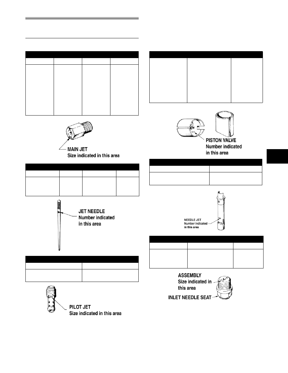
Components
* For models with carburetor switch
MAIN JETS AVAILABLE
JET
P/N
JET
P/N
130
6505-216
210
6505-145
140
6505-217
220
6505-137
150
6505-168
230
6505-067
160
6505-064
240
6505-079
170
6505-065
250
6505-068
180
6505-056
260
6505-017
190
6505-066
270
6505-069
200
6505-144
280
6505-080
JET NEEDLES AVAILABLE
JET NEEDLE
P/N
JET NEEDLE
P/N
6CE25
6506-408
6DH3
6505-509
6CH3
6505-519
6DH4
6505-003
6DH2
6505-252
6DH7
6505-215
PILOT JETS AVAILABLE
JET NO.
P/N
35
6505-029
40
6505-047
PISTON VALVES AVAILABLE
SLIDE
CARB. SIZE (mm)
P/N
2.5
32-34
6505-246
3.5
32-34
6505-248
2.5
34
6505-500
2.5
34
6505-614*
3.0
34
6505-507
3.0
34
6505-561*
NEEDLE JETS AVAILABLE
NEEDLE JET
P/N
P-4M (961)
6506-407
P-5M (953)
6506-405
INLET NEEDLE ASSEMBLIES AVAILABLE
SEAT DIA.
CARB. SIZE (mm)
P/N
1.5 mm (Steel)
28, 30, 32, 34
6505-026
1.5 mm (Viton)
28, 30, 32, 34
6505-160
1.5 mm (Steel)
28 — 34 GVM
6505-245