Snowmobile Arctic Cat (2002 year). Manual - part 113


  Index      Snowmobiles / ATV     Snowmobile Arctic Cat - service manual 2002 year


Search            


Content   ..  111  112  113  114   ..


Snowmobile Arctic Cat (2002 year). Manual - part 113


8-10

6. Either test drive the snowmobile or run the engine

for five minutes; then tighten the drive clutch bolt

to 6.9-7.6 kg-m (50-55 ft-lb).

REPLACING CAM ARM BUSHINGS

1. Using a vise, spread the jaws just enough to allow

room for the bushing to pass between.

2. Position the cam arm over the spread jaws.

AM094

3. Slide a new bushing onto one of the cam arm pins;

then position the pin through the cam arm bushing.

AM095

4. Using the new bushing as a tool, drive the worn

bushing from the cam arm. When the head of the

cam arm pin contacts the cam arm, the new

bushing will be properly seated.

AM096

Driven Pulley

REMOVING

1. Open the hood; then open the belt guard.

2. Remove the drive belt.

3. Remove the cap screw and washer securing the

driven pulley; then account for and note the

position of any alignment washers.

SC013D

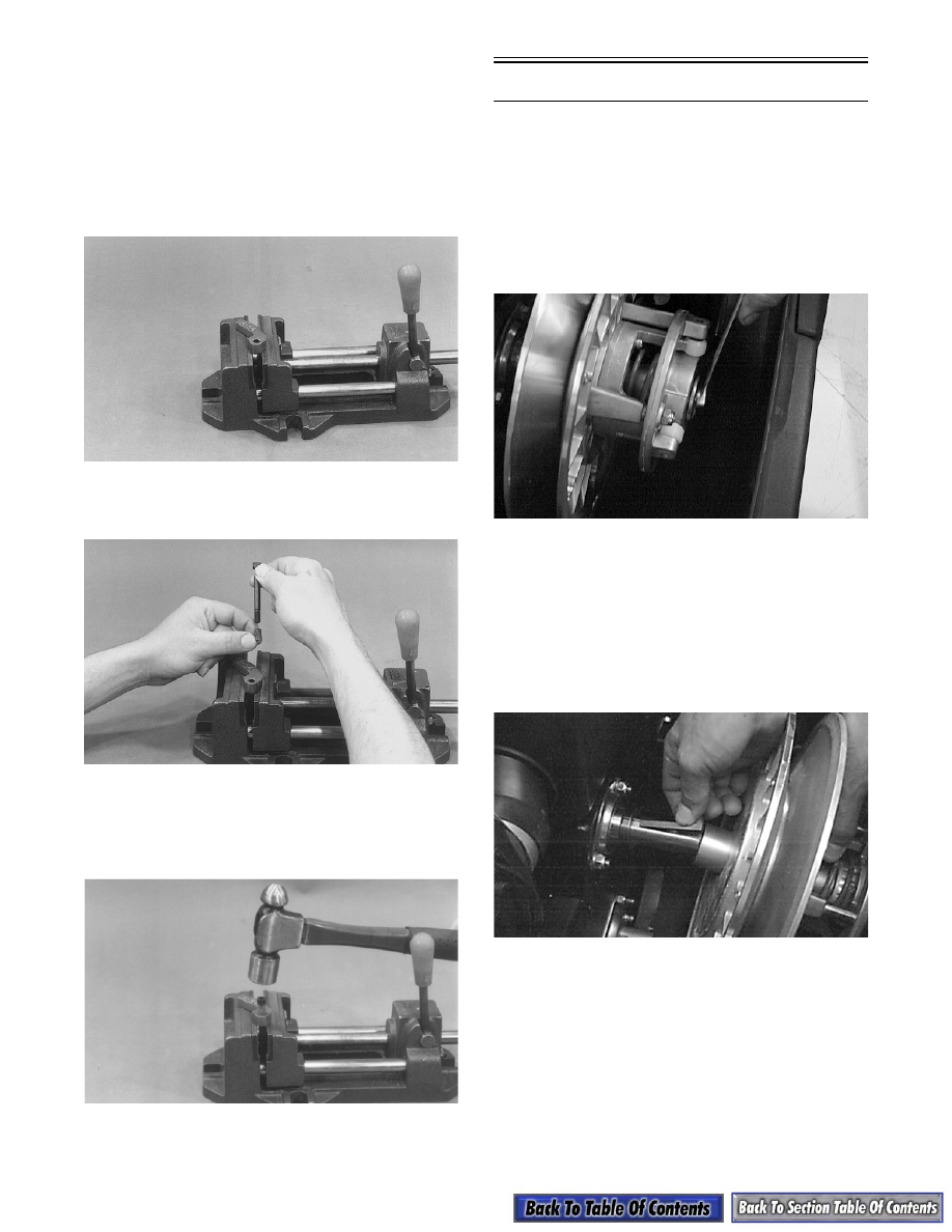
4. Slide the driven pulley off the driven shaft; then

remove pulley from the engine compartment.

„ NOTE: If the driven pulley is tight on the shaft,
pull the driven pulley off using the Driven Pulley
Puller (p/n 0744-023).

5. Remove the key, alignment washers, and stub

shaft from the driven shaft.

AF120D

8-11

8

DISASSEMBLING

1. Scribe a line across all driven pulley components

to ensure correct assembly and pulley balance.

SC001D

2. Place the driven pulley on a work fixture so the

roller plate is directed upward.

SC002D

„ NOTE: To aid in driven pulley servicing, use a
roll of duct tape as a work fixture. The work fixture
will increase the stability of the pulley during the
repair procedure.

3. Remove the three lock nuts securing the roller

plate; then carefully slide the plate off the

stationary shaft allowing the spring to release

tension.

SC003D

4. Remove the spring.

B458D

5. Slide the movable sheave off the stationary shaft;

then remove any thrust washers located between

the sheaves noting the position of washers for

assembling purposes.

B459D

B460

! WARNING

The roller plate is under spring pressure. Care must
be taken when removing the lock nuts to prevent
the plate from ejecting prematurely.

8-12

6. Remove the three socket head screws and lock

washers securing the torque bracket (cam) to the

stationary sheave; then remove torque bracket.

AI062

7. Place the roller plate on a work fixture (roll of duct

tape, etc.).

SC004D

8. Using a 1/8-in. punch, remove the spring pin

securing the roller, roller pin, and thrust washer to

the plate.

SC005D

9. Using the Roller Pin Removal Tool (p/n 0644-

276) from inside the plate, drive the roller pin out

of the plate. Account for the pin, thrust washer,

and roller.

SC006D

SC007D

CLEANING AND INSPECTING

„ NOTE: Whenever a part is worn excessively,
cracked, or damaged in any way, replacement is
necessary.

1. Using parts-cleaning solvent, wash grease, drive

belt dust, and foreign matter off all components.

2. Inspect the rollers for damage, cracks, or wear.

3. Inspect the sheaves for any gouges, cracks, or

other damage. Also, inspect threaded areas of

sheaves for damaged or stripped threads.

4. Inspect the torque bracket (cam) for cracks or

damage. The ramp portions of the bracket and

caps must be free of gouges and damage. Minor

scratches may be repaired using #320 grit wet-or-

dry sandpaper.

! CAUTION

Do not use steel wool or a wire brush to clean
driven pulley components. A wire brush or steel
wool will cause the sheaves to be gouged (thus,
the drive belt may not slide properly between
sheaves). Decreased performance and possible
accelerated drive belt wear will result.

8-13

8

B465

5. Inspect spring for distortion, crystallization, or

breaks.

6. Inspect the roller plate, rollers, pins, and spring

mounting holes for cracks, damage, or wear.

7. Inspect the roller plate and movable sheave

bearings for wear. For each respective bearing,

measure the outside diameter of the shaft and the

inside diameter of the bearing. Compare the

readings. Clearance between the shaft and the

respective bearing must not exceed 0.5 mm

(0.020 in.). If the clearance exceeds the

specification, the bearing must be replaced.

B466D

B467

REMOVING BEARINGS

To remove driven pulley bearings, use the Bearing

Removal and Installation Tool (p/n 0644-167) and the

following procedure.

„ NOTE: To remove the movable sheave bearing,
heat must be applied around the bearing.

1. Place the movable sheave (or roller plate) flat on a

press.

2. Using the bearing tool, press the bearing out.

AF154

INSTALLING BEARINGS

„ NOTE: Before installing a bearing, apply red
Loctite #271 to the outside face of the bearing.

1. Place the movable sheave (or roller plate) flat on a

press.

2. Using the bearing tool, press the bearing into

position. The bearing must be flush with the

outside of the bearing boss.

3. Wipe off excess Loctite. Allow the Loctite to cure

for 24 hours at room temperature.

! WARNING

Always wear safety glasses when using the bearing
driver.


Content   ..  111  112  113  114   ..