Snowmobile Yamaha RX1 (2003 year). Manual - part 17
8-15
ESU00166
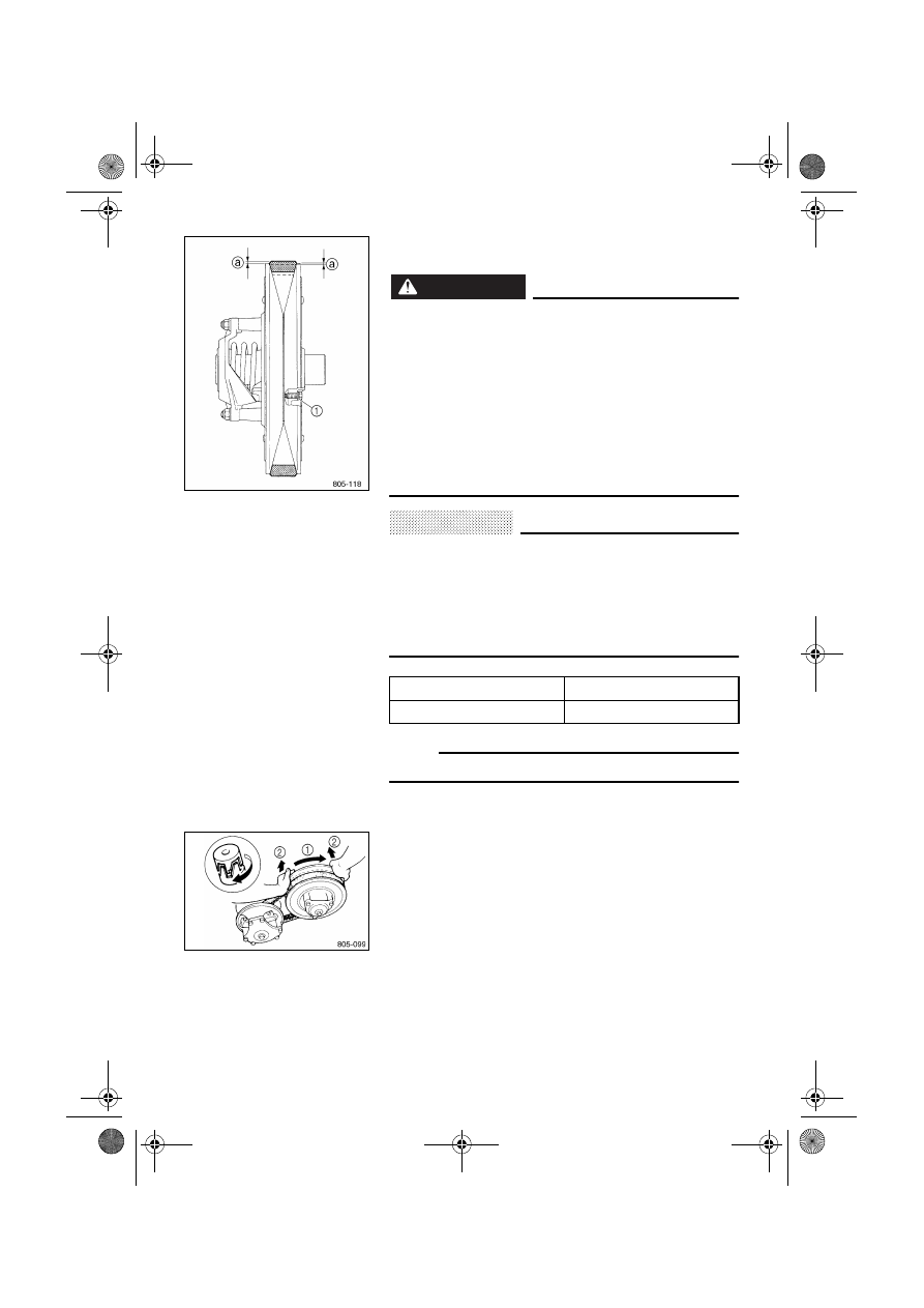
V-belt replacement
WARNING
@
When installing the new V-belt, make sure it is posi-
tioned from 1.5 mm (0.06 in) above the edge of the
secondary sheave assembly to 0.5 mm (0.02 in)
below the edge
a.
If not, the V-belt clutch engagement speed will be
changed. The snowmobile may move unexpectedly
when the engine is started.
Adjust the V-belt position by removing or adding a
spacer
1 on each adjusting bolt.
Have a Yamaha dealer make this adjustment.
@
CAUTION:
@
As the V-belt wears, adjustment may be necessary.
To ensure proper clutch performance, the V-belt
position should be adjusted by adding a spacer on
each adjusting bolt when the V-belt position reaches
1.5 mm (0.06 in) below the edge.
Have a Yamaha dealer make this adjustment.
@
CD-05E
NOTE:
@
Apply the parking brake before replacing the V-belt.
@
1. Remove the drive guard.
2. Rotate the secondary sliding sheave clockwise
1
and push
2 it so that it separates from the secondary
fixed sheave.
New belt width
34.5 mm (1.36 in)
Belt wear limit width
32.5 mm (1.28 in)