Snowmobile Yamaha Phazer PZ50 (2007-2008 year). Manual - part 63
6-11
COOL
ASSEMBLY
1. Install:
• Oil seal 1
(to the water pump housing)
NOTE:
• Before installing the oil seal, apply tap water or
coolant onto its outer surface.
• Install the oil seal with a socket that matches its
outside diameter.
2. Install:
• Bearing
NOTE:
Install the bearing with a socket that matches its
outside diameter.
New
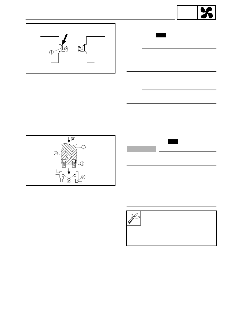
3. Install:
• Water pump seal
CAUTION:
Never apply oil or grease onto the water pump
seal surface.
NOTE:
• Install the water pump seal 1 with the mechani-
cal seal installer 4 and 40 and 50 mm bearing
driver 5.
• Before installing the water pump seal, apply
Yamaha bond No.1215 2 to the water pump
housing 3.
È Push down
Mechanical seal installer:
90890-04145, YM-04145
40 and 50 mm bearing driver:
90890-04058, YM-04058
Yamaha bond No. 1215:
90890-85505
(Three Bond No.1215
®
)
New