Snowmobile Yamaha FX10X, FX10RTX, FX10RTRX, FX10RTRAX, FX10MTX, FX10MTRX, FX10MTRAX. Manual - part 78
8-6
–
+
ELEC
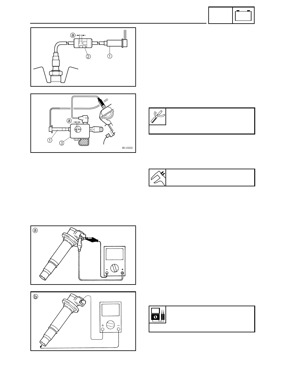
IGNITION SPARK GAP
The following procedure applies to all of the ignition
coils.
1. Measure:
• Ignition spark gap
Out of specification
→ Replace the ignition
coil(s).
Measurement steps:
• Disconnect the ignition coil 1 from the spark
plug.
• Connect the opama pet-4000 spark checker 2
or ignition checker 3.
• Measure the ignition spark gap
a.
• Crank the engine by setting the engine stop
switch to “RUN” and turning the main switch to
start and gradually increase the spark gap until
a misfire occurs.
È For USA/Canada
É For Europe
Opama pet-4000 spark checker:
YM-34487
Ignition checker:
90890-06754
Ignition spark gap:
6.0 mm (0.24 in)
È
É
IGNITION COIL
The following procedure applies to all of the ignition
coils.
1. Disconnect:
• Ignition coil coupler
2. Connect:
• Pocket tester
(to the ignition coil)
3. Measure:
• Primary coil resistance
a
• Secondary coil resistance
b
Out of specification
→ Replace the ignition
coil(s).
Primary coil resistance:
1.19 ~ 1.61
Ω at 20 °C (68 °F)
Secondary coil resistance:
8.5 ~ 11.5 k
Ω at 20 °C (68 °F)