Snowmobile Yamaha FX10X, FX10RTX, FX10RTRX, FX10RTRAX, FX10MTX, FX10MTRX, FX10MTRAX. Manual - part 9
2-25
INSP
ADJ
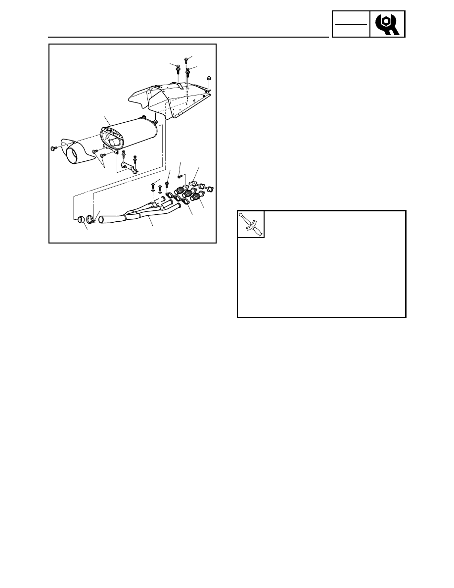
EXHAUST SYSTEM INSPECTION
1. Remove:
• Fuel tank
Refer to “SEAT AND FUEL TANK” in CHAP-
TER 5.
2. Inspect:
• Exhaust pipe joints 1
• Exhaust pipe 2
• Muffler 3
• Exhaust pipe bands 4
• Muffler band 5
Cracks/damage
→ Replace.
• Exhaust pipe joint gasket 6
• Muffler gasket 7
Exhaust gas leaks
→ Replace.
3. Inspect:
• Tightening torque
4. Install:
• Fuel tank
Refer to “SEAT AND FUEL TANK” in CHAP-
TER 5.
T
R
.
.
Exhaust pipe joint bolt 8:
25 Nm (2.5 m · kg, 18 ft · lb)
Exhaust pipe band bolt 9:
9 Nm (0.9 m · kg, 6.5 ft · lb)
Muffler bolt (rear side) 0:
23 Nm (2.3 m · kg, 17 ft · lb)
Muffler bolt (front side) A:
23 Nm (2.3 m · kg, 17 ft · lb)
Muffler band bolt B:
20 Nm (2.0 m · kg, 14 ft · lb)
Exhaust pipe bolt C:
23 Nm (2.3 m · kg, 17 ft · lb)
A
8
9
B
A
5
2
C
6
7
3
0
1
(6)
(3)
4