Snowmobile Polaris 600 RUSH (2010 year). Manual - part 82
 

  Index      Snowmobiles / ATV     Snowmobile Polaris 600 RUSH - service manual 2010 year


Search            


Content   ..  80  81  82  83   ..


Snowmobile Polaris 600 RUSH (2010 year). Manual - part 82


10.24

Battery and Electrical Systems

9923311 - 2010-2012 PRO-RIDE RUSH/Switchback/RMK Service Manual

© 2011 Polaris Sales Inc.

DC-CFI ELECTRICAL SYSTEMS

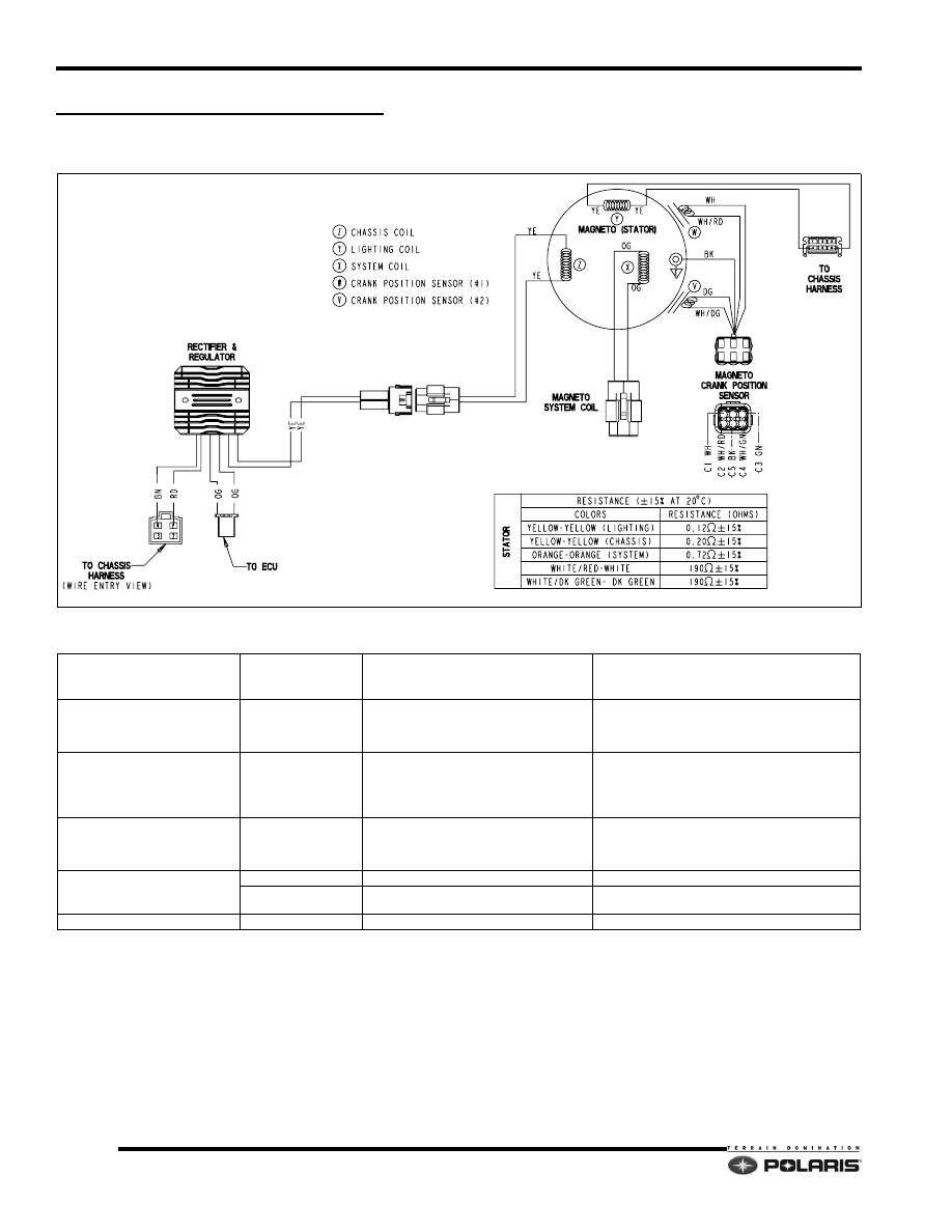
DC-CFI Stator Assembly

DC-CFI Stator Specifications

ITEM

COLOR

SYSTEM FUNCTION

RESISTANCE

+/- 15% @68

°

F (20

°

C)

AC Lighting Coil (Y)

YELLOW to YELLOW

14VAC Chassis Power

 - Battery Charge (Electric Start Equipped)

 - Head / Tail Lights

 - Hand / Thumb Warmers

YELLOW TO YELLOW = 0.12



NO CONTINUITY TO GROUND

DC Chassis Coil (Z)

YELLOW to YELLOW

14VDC Chassis Power

 - Fuel Pump

 - Chassis Relay Coil

 - EV Solenoid

 - Instrument Cluster

YELLOW TO YELLOW = 0.20



NO CONTINUITY TO GROUND

DC System Coil (X)

ORANGE to ORANGE

16 VDC System Power

 - Fuel Injector Power

 - ECU / Sensor Power (Regulated to 5VDC)

 - Ignition Coil Power

ORANGE TO ORANGE = 0.72



NO CONTINUITY TO GROUND

CRANK POSITION SENSOR (CPS)

GRN to WHT/GRN

Crank Position Sensor (5 Tooth) Ignition timing GRN to WHT/GRN = 190

WHT to WHT/RED

Crank Position Sensor (2 Tooth)

Locates TDC and RPM

WHT to WHT/RED = 190

ENGINE GROUND

BROWN

Engine Ground

0

10.25

Battery and Electrical Systems

10

9923311 - 2010-2012 PRO-RIDE RUSH/Switchback/RMK Service Manual

© 2011 Polaris Sales Inc.

DC Regulator/Rectifier

DC-CFI Chassis Power Capacitor

Capacitor Testing

1. Charge the capacitor for 10 seconds using a 12 volt 

battery by connecting the positive (+) lead to the Red/
White wire and the negative (-) lead to the brown wire.

2. Monitor the capacitor voltage with a multimeter. The 

voltage should slowly drain down from the initial 
charge. If the cap does not hold a charge or drains 
rapidly, replace the component.

DC-CFI AC Regulator/Battery Charge 

Rectifier

DC-CFI models feature an AC regulator/DC (battery 
charge) rectifier. The AC regulator/battery charge rectifier 
only regulates AC voltage and charges the battery (when 
equipped). It does not supply VDC to the instrument 
cluster or accessory power points.

DC-CFI Regulator / Rectifier Connections

CONNECTOR

WIRE 

COLORS

ITEM

Stator

YELLOW VAC from stator coils.

ECU

ORANGE

VDC supplied to ECU to 
boost power to fuel pump 
during engine start-up.

Chassis

BROWN 14.5 VDC Chassis power.

(Instrument cluster/EV 
solenoid/DC power points)

RED

Circuit Specifications

PLUG

/

PIN

/

COLOR

FUNCTION

1 - RED/DK. GREEN

14.7DCV BATTERY (+)

2 - YELLOW

14.3 ACV (FROM STATOR)

3 - BROWN

GROUND (-)

10.26

Battery and Electrical Systems

9923311 - 2010-2012 PRO-RIDE RUSH/Switchback/RMK Service Manual

© 2011 Polaris Sales Inc.

Ignition Coil Packs

Exhaust Valve Solenoid

Oil Level Sender

To test the oil level sender, position the sender as it would 
be in the oil tank. Allow the float to drop in the direction it 
would if the oil tank were empty. Continuity should be 
present when using a multimeter to test the sender with 
the float in the “empty” position. 

No continuity should be present when the float is moved 
away from the “empty” position.

LH Control Assembly

Test the left hand (LH) control assembly using a 
multimeter set to show continuity. Reference the 
illustration below for continuity checks.

Specifications

Coil Pack

Wires/Leads

600 DC-CFI-4

600/800

DC-CFI-2

+/- 15% @ 68°F (20°C)

BLACK to WHITE 
(Primary)

0.20

0.45

BLACK to

Secondary Lead

6.3K

18K

Plug cap

5K

Specifications

Coil Resistance

(WH/YE to RED)

15

 +/- 15% @ 68°F (20°C)

FULL

EMPTY (CONTINUITY)

10.27

Battery and Electrical Systems

10

9923311 - 2010-2012 PRO-RIDE RUSH/Switchback/RMK Service Manual

© 2011 Polaris Sales Inc.

DC-CFI Regulated (Red) Power Circuits

REGULATED DC

VOLTAGE

CH / ENG GROUND

DC CHASSIS VOLTAGE

RED/WHT

RED

BRN -- DIRECT

DC--CFI ECU 3 4   P I N CNA CONNECTOR

20

REGULATOR

RECTIFIER

YELLOW

AC STATOR

VOLTAGE

21

CAPACITOR

33

CHASSIS RELAY

ORG

ORG

WH/DB

RED

RED/WHT

ORANGE

M

19

FUEL PUMP

FUEL

PUMP

PRIME

PLUG

EV SOLENOID

30

34

17

EXT.

POWER

PLUG

DIGITAL

WRENCH

PLUG

EXTERNAL POWER

RED

WHT/YEL

RED

ORG

ORG

BRN/YEL

RED

ORG


Content   ..  80  81  82  83   ..