Snowmobile Polaris Trail RMK (2010 year). Manual - part 20
81
MAINTENANCE
Brakes
n
Hydraulic Brake Inspection
Inspect the brake lever reserve before each use of the snowmobile. See
page 45.
Brake pads must be replaced when the brake pad material becomes thin-
ner than the backing plate (approximately 1/16 inch/1.5 mm). A kit is
available for replacing brake pads. See your dealer.
WARNING! Brake failure during operation can result in serious injury or death.
Properly functioning brakes are vital to your safety. Be sure the brake pads do
not drag on the disc and that brake lever travel is not excessive. Always replace
brake pads when the brake pad material becomes thinner than the backing plate
(approximately 1/16 inch/1.5 mm).
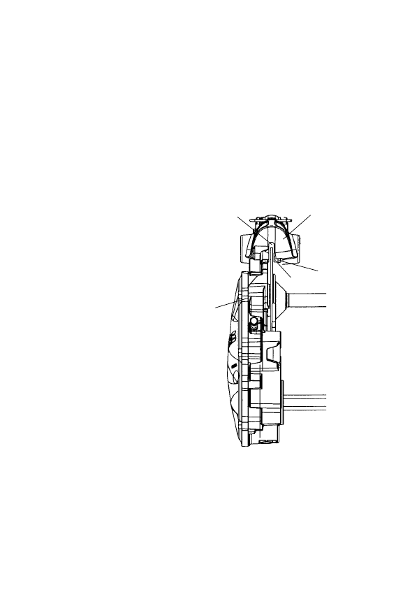
Brake Components
1. Brake Caliper
2. Chaincase
3. Brake Disc
4. Backing Plate
5. Brake Pad Material
(Replace when thickness is
less than 1/16 inch/1.5 mm)
1
2
3
4
5