Snowmobile Polaris High Performance (2001 year). Manual - part 88


  Index      Snowmobiles / ATV     Snowmobile Polaris High Performance - service manual 2001 year


Search            


Content   ..  86  87  88  89   ..


Snowmobile Polaris High Performance (2001 year). Manual - part 88


ELECTRICAL

8.11

Multimeter Usage

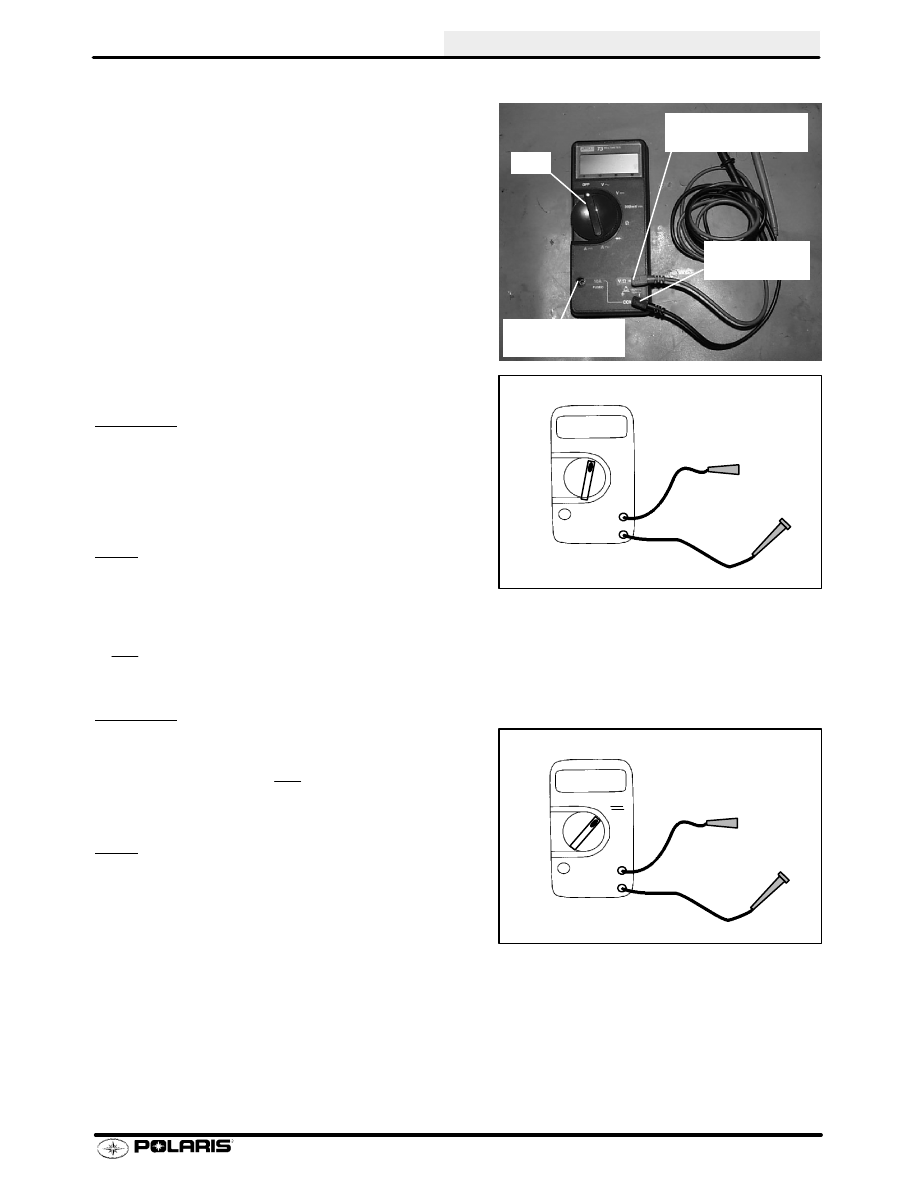
The easiest and most accurate method for testing modern
electrical components is with a digital multitester. Any good
quality multitester will work. However, due to ease of opera-
tion and durability, Polaris recommends the Fluke Model 73
(PN 2870659), or Tektronix DMM155. See photo at right.
This instrument will provide a digital readout of the measured
value of the test being performed.

Listed below are the dial symbols, their meaning and what
the dial setting can be used for.

Off = Instrument Off

V

~

= Volts AC - measuring alternator output

Used to measure AC voltage in an electrical system. AC volt-
age is produced from every coil on the stator plate when a
magnet is passed by it.

Test Method

1.

Connect black lead to Com (--) meter terminal.

2.

Connect red lead to V

τ

(+) meter terminal.

3.

Turn selector dial to V

~

setting.

4.

Connect test leads parallel with test component. The
polarity of the leads is not important.

Usage

S

Test unregulated voltage output of a stator coil

S

Test regulated voltage to the lights and handwarm-
ers

- - - = Volts DC - measuring battery voltage, volt drop, etc.

Used to measure DC voltage produced by a battery or rectifier.

Test Method

1.

Connect black lead to Com (--) meter terminal

2.

Connect red lead to V

τ

(+) meter terminal.

3.

Turn selector dial to V - - - setting.

4.

Connect test leads parallel with test component.
Observe polarity.

Usage

S

Test battery voltage

S

Test DC regulator

S

Test voltage drop for bad connections

S

Test supply voltage to electric fuel gauge

Dial

Red Lead here
for Volts and Ohms

Common
(Black Lead)

Red Lead here
for Amperes

+

_

17.29

V

~

VAC

+

_

12.95

V

VDC

ELECTRICAL

8.12

Multimeter Usage

τ

= Ohms, resistance - measuring component resistance values - testing coils, wiring, etc.

Used to test resistance to the flow of electricity in a circuit or
component. A reading of OL means an open circuit or infinite
resistance. Sometimes the leads themselves will have some
resistance. Touch the leads together and subtract this resis-
tance from the component reading to achieve the actual
reading.

Test Method

1.

Connect black lead to Com (--) meter terminal

2.

Connect red lead to V

τ

(+) meter terminal.

3.

Turn selector dial to

τ

setting.

4.

Isolate test component from the rest of the electrical
circuit by disconnecting wires from harness.

5.

Connect test leads to the circuit to be tested.

Usage

S

Testing coil resistance

S

Testing switch operation

S

Testing wire continuity

A

~

= Amps AC - used to test lighting coil output

Used to test the power of an alternator coil.

Test Method

1.

Connect black lead to Com (--) meter terminal

2.

Connect red lead to 10A (+) meter terminal.

3.

Disconnect engine harness from system.

4.

Connect across the specified coil wires.

5.

Start engine and let it idle.

6.

Readings should be above 5 Amps at any RPM. NOTE:
It is not necessary to increase RPM. The reading can be
obtained at idle.

Usage

S

Testing stator coil power output.

+

_

00.2

τ

τ

+

_

14.00

A

~

AC

ELECTRICAL

8.13

Unregulated Voltage - continued

7.

Turn the multitester dial to the Volts AC (V

µ

) position.

8.

Disconnect the alternator to main harness connector at
engine.

9.

Connect one of the tester leads to the yellow alternator
wire and the other lead to the brown alternator wire.
NOTE: On floating alternators, the yellow/red stator
wire should connect to the brown stator wire. If it does
not, the system will not have a ground and will not
operate.

10. Start the engine. While observing the voltage reading,

increase the engine speed to about 3000 RPM.
Readings of between 15 and 45 VAC are considered
normal.

Short Circuit Current (AC Amp Test)

1.

Turn multitester dial to A

µ

.

2.

Connect red lead to 10A terminal.

3.

Connect black lead to Com (--) meter terminal.

4.

Disconnect lighting/charge coil wires from system.
Connect meter leads to coil wires leading to stator coils.

5.

Start and idle engine. Readings should be above 5
amps. Refer to Amps AC on page 8.12.

Regulated Voltage

1.

Connect the alternator to main harness connector.

2.

Insert one of the tester leads along the side of the yellow
regulator wire connector between the insulation and the
terminal.

3.

Ground the other tester lead.

4.

Start engine and observe headlight output. Increase
engine RPM. If the headlights seem dim above 3500
RPM, let the engine return to idle and disconnect the
yellow wire from the regulator. Carefully observe the
voltage reading. Do not allow voltage to increase above
14.0 volts.

5.

Slowly increase RPM. Voltage above 12 volts at 2500 -
3000 and a bright headlight, indicates a good lighting
coil. Voltage below 10 volts at 3000 indicates excessive
system loads, poor flywheel magnets, lighting coil
problems, or wires harness problems.

Check for

partially grounded (shorted) yellow wire.

6.

Reconnect the yellow regulator wire and increase the
RPM. If the headlight was bright with the regulator
disconnected and dim when connected at the same
RPM, the regulator or regulator ground is at fault.

+

_

15-45

V

~

VAC

ELECTRICAL

8.14

Alternators

The 6 pulse alternator system is the number of AC sine waves created by the alternator in one revolution of the
crankshaft. For example, in a 6 pulse system, the alternator will create 6 pulses, or 6 complete AC sine waves, in
one crankshaft revolution. The tachometer reads these sine waves, therefore giving you accurate RPM readings.
A 3 pulse tachometer cannot be used on a 6 pulse system. If this is done, the tachometer will read double RPM.
Refer to the following text for applications.

Polaris Snowmobiles:

All Polaris Domestic twin cylinder engines

6 pulse

. . . . . . . . . . . . . . . . . . . . . . . . . .

Fuji 3 cylinder engine

6 pulse

. . . . . . . . . . . . . . . . . . . . . . . . . . . . . . . . . . . . . . . . . . . .

Fuji Fan Cooled EC45/55PM

6 pulse

. . . . . . . . . . . . . . . . . . . . . . . . . . . . . . . . . . . . . .

Tachometers:

Tachometers for snowmobiles will have an identification marking on the back side. For example: The tachomter
for a 600 RMK will have “6 pulse” (or 6P) written on it.

6-Pulse


Content   ..  86  87  88  89   ..