Snowmobile Polaris High Performance (2001 year). Manual - part 79


  Index      Snowmobiles / ATV     Snowmobile Polaris High Performance - service manual 2001 year


Search            


Content   ..  77  78  79  80   ..


Snowmobile Polaris High Performance (2001 year). Manual - part 79


REAR SUSPENSION/TRACK/TRACTION

7.27

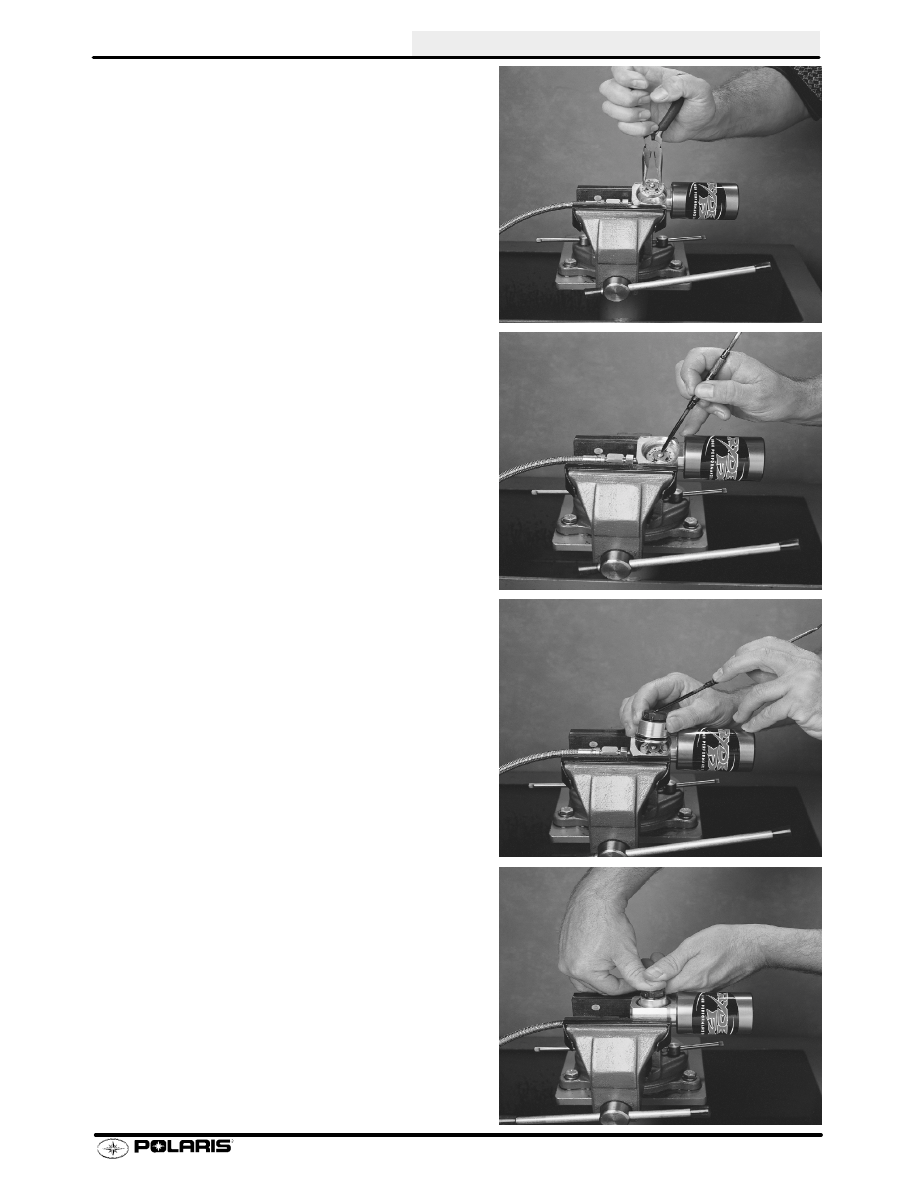
Remove the compression head from the clicker as-
sembly housing by grasping the compression pin
with pliers and pulling straight out. (Picture 25)

ASSEMBLY:Install the compression head into the
clicker assembly housing, making sure the com-
pression pin is facing up. (Picture 26)

Fill compression housing with approximately 10cc
of shock fluid.

Set the compression clicker to the zero 0 position.
(Picture 27)

Pushing firmly down, reinstall clicker assembly into
housing. Special attention should be given to en-
sure the pin is positioned in the same location as it
was prior to removal. (Picture 28)

25

26

27

28

REAR SUSPENSION/TRACK/TRACTION

REAR SUSPENSION/TRACK/TRACTION

7.28

Pressurize the shock reservoir, through the pres-
sure valve, with nitrogen gas to the specified pres-
sure. (PICTURE 29)

If using RydeFX inflation tool Refer to Procedures
for use of replaceable inflation Needle instruction
manual found in RydeFX Inflation Tool case.

NOTE: -- Depending on which shock absorber is be-
ing worked on, adjust the gas pressure the specified
value indicated in the shock specification chart lo-
cated (TBD) service manual.

After being compressed ,the piston rod should be
fully extended from the shock body once the shock
has been pressurized.

Install the small button head screw in the pressure
valve assembly and tighten securely. (PICTURE
30)

29

30

REAR SUSPENSION/TRACK/TRACTION

7.29

Arvin Valve Washer Part Numbers Fox

t

t

t

t

Part Numbers on pg 7.14

Polaris #

Thickness

Diameter

1700080

0.004

0.700

1700081

0.006

0.700

1700082

0.008

0.700

1700083

0.010

0.700

1700084

0.012

0.700

1700085

0.015

0.700

1700086

0.004

0.800

1700087

0.006

0.800

1700088

0.008

0.800

1700089

0.010

0.800

1700090

0.012

0.800

1700091

0.015

0.800

1700092

0.004

0.900

1700093

0.006

0.900

1700094

0.008

0.900

1700095

0.010

0.900

1700096

0.012

0.900

1700120

0.015

0.900

1700121

0.006

1.000

1700122

0.008

1.000

1700126

0.010

1.000

1700127

0.012

1.000

1700128

0.015

1.000

1700129

0.006

1.100

1700130

0.008

1.100

1700131

0.010

1.100

1700132

0.012

1.100

1700133

0.015

1.100

1700134

0.006

1.250

1700135

0.008

1.250

1700136

0.010

1.250

1700137

0.012

1.250

1700138

0.015

1.250

1700139

0.006

1.300

1700140

0.008

1.300

1700141

0.010

1.300

1700142

0.012

1.300

1700143

0.015

1.300

Tool Part numbers:

Gas Fill Tool and Gague (Incl. 5 needles)

PS45259

Gas Fill Needles replacement pack

PS45259--1

Gas Fill Gague (replacement)

PS45259--2

Lower Retainer Wrench

PS45260

IFP Positioning / Extraction tool

PS45261

Cylinder Head Wrench

PS45262

Wear Band Tool

PS45263

Arvin Shock Body Holder

PS45629

REAR SUSPENSION/TRACK/TRACTION

REAR SUSPENSION/TRACK/TRACTION

7.30

Fox

Shock Maintenance

Changing oil on Fox

Shocks is recommended annually and should be included when performing end of season

storage preparation. This oil change is necessary to avoid any chance of corrosion which could be caused by
moisture contamination. For competition use, shocks should be disassembled, inspected and serviced more fre-
quently.

When performing maintenance on Fox

Shocks, use Gas Shock Recharging Kit PN 2200421. It consists of the

necessary valves, pressure gauge, and fittings to deflate and pressurize the shocks. The Body Holder Tool, Inter-
nal Floating Piston (IFP), and Shock Rod Holding Tool are not included in the Recharging Kit and must be ordered
separately. Refer to your Victor Specialty Tool catalog for part numbers.

WARNING

Extreme caution should be observed while handling and working with high pressure service equipment. Wear
a face shield, safety glasses, and ear protection during service of these shocks.

Care should be observed while handling the inflater needle and pressure gauges. Maintain your equipment and
keep it in good condition. If injury should occur, consult a physician immediately.

Extreme cleanliness is of utmost importance during all disassembly and reassembly operations to prevent any
dirt or foreign particles from getting into the shocks.

Keep the parts in order as they are disassembled. Note the direction and position of all internal parts for reas-
sembly.

Ref. # Qty.

Description

1

1

Pressure Valve

2

2

O-Ring

3

1

Retaining Ring

4

1

Spring Retainer Body

5

2

O-Ring

6

1

Piston Ring (Floating)

7

1

Piston Ring (Damping)

8

1

Spring Retainer, Slotted

For Fox

t

shock maintenance, refer to 2000 service manuals.

Gas Shock Recharging Kit

PN 2200421

1

3

4

6

5

5

8

7

Internal Floating
Piston (IFP)

Shock Body

Bleed Screw

2

Body Cap

Bearing
Cap

Jounce
Bumper

Damper Rod

REAR SUSPENSION/TRACK/TRACTION


Content   ..  77  78  79  80   ..