Snowmobile Polaris (2006 year). Manual - part 42
7.22
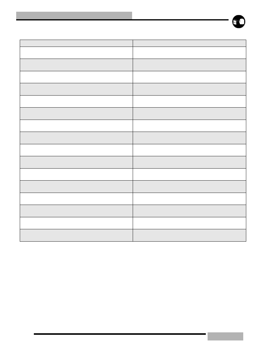
CLUTCHING
Table 7-9: Team Driven Ramps for Non Electric Reverse
PART NUMBER
DESCRIPTION
5133321
66/44-46
70/48-36
5133491
74/48-46
70/48-46
5133492
74/48-46
74/40-46
5133493
72/44-46
72/40-46
5133494
70/44-46
70/40-46
5133495
68/44-46
68/40-46
5133496
66/48-46
66/40-46
5133497
64/44-46
64/40-46
5133498
62/44-46
62/40-46
5133499
58/44-46
58/40-46
5133721
66/44-46
70/48-46
5134566
58/42-36
56/40-40
5134746
64/38-65
66/40-55
5134861
58/34-46
60/34-65
5135375
62/40-46
64/40-55
5135376
64/38-65
64/38-46