Kincaid 8xp. Manual - part 2
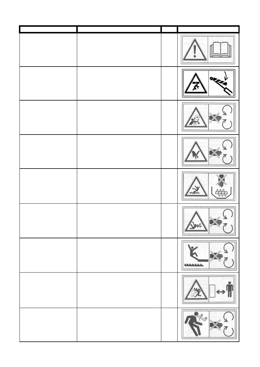
Hazard pictorials
Danger
How to avoid it
Nr.
Symbol
Subject to danger due to
insufficient information
Read the manual before starting the com-
bine
1
A raised part may fall down Support raised parts before going under
them
2
Gap in belt drive
Stop the engine and remove the ignition
key before removing any guards
3
Getting entangled in mov-
ing parts
Stop the engine and remove the ignition
key before removing any guards and/or
reaching into a danger zone
4
Getting entangled in rotat-
ing auge
Stop the engine and remove the ignition
key before removing any guards
5
Getting entangled in rotat-
ing auger
Do not reach into an opening with the en-
gine running
6
Falling into moving machin-
ery
Stop the engine and remove the ignition
key before removing any guards
7
Danger caused by flying
objects
Keep at a safe distance from the combine
8
Kickback or upward motion
of arm handle
Stop the engine and remove the ignition
key before inserting the handle
9
- 11 -