Challenger Terra Gator 3244 Chassis. Manual - part 125


  Index      Challenger     Challenger Terra Gator 3244 Chassis - service repair manual 2009 year


Search            


Content   ..  123  124  125  126   ..


Challenger Terra Gator 3244 Chassis. Manual - part 125


627333-A  

8-7

Air Tank and Pressure Control Check Valve

Air Tank Installation

NOTE: For example ew use the wet air tank.

NOTE: Always use new O-rings and O-ring washers.

NOTE: Be sure to apply a thin film of oil to the O-rings

on all fittings.

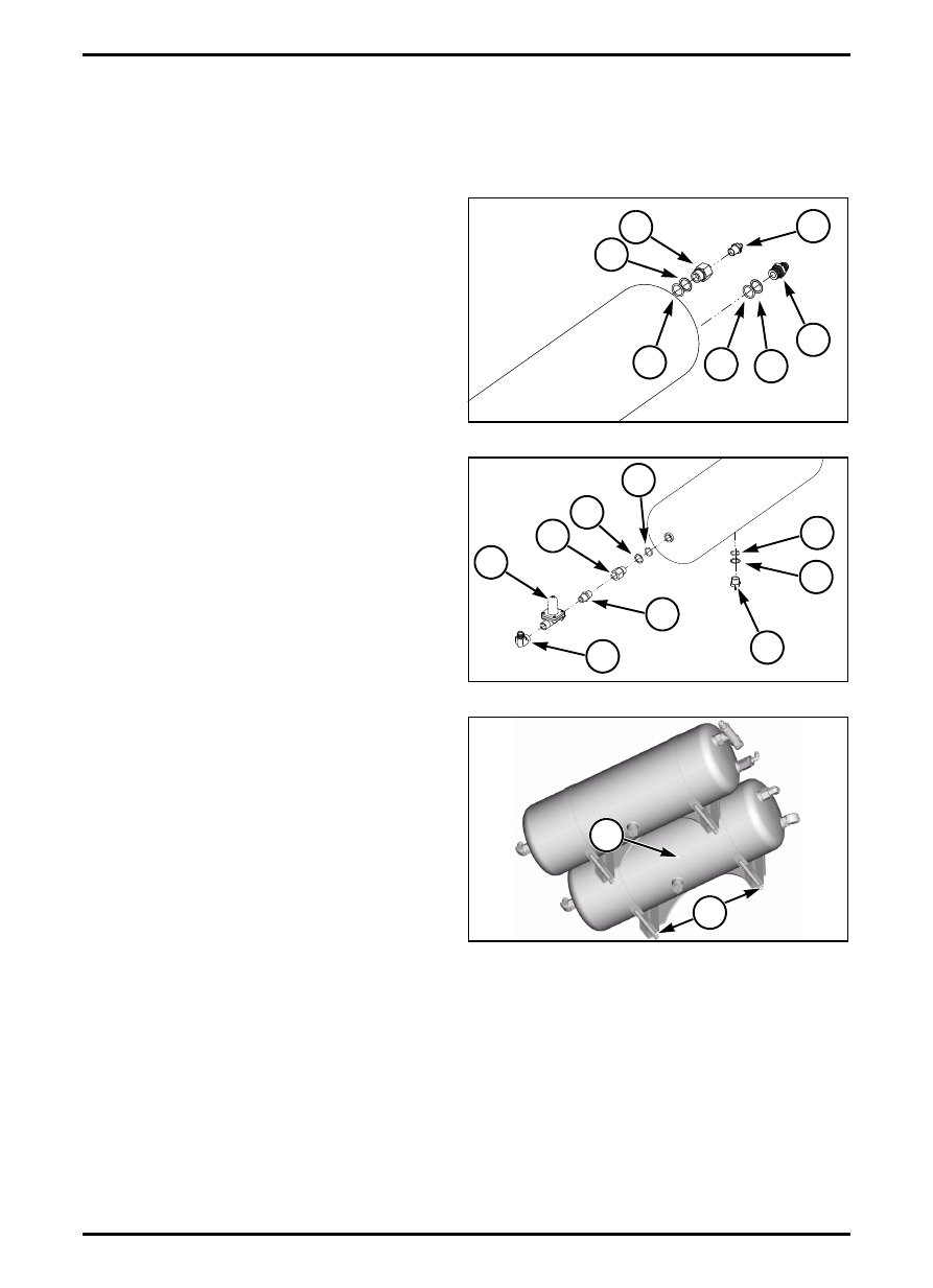
FIG. 4: Install 3/4-16 MJIC straight adapter (1) into

inlet port with M22 O-ring (2) and M22 trust washer (3).

Install 3/8 MNPT x 1/4 MJIC adapter (4) into a

M22-1-1/2 OR x 3/8 FNPT adapter (5). Install this

assembly into output port on rear of tank with M22

O-ring (6) and M22 trust washer (7).

FIG. 5: Install drain valve (1) into port in bottom of tank

with M22 O-ring (2) and M22 trust washer (3).

Install 8 FNPT x 8 MJIC 90-degree fitting (4) onto outlet

port of PCCV (5). Tighten fitting until vertical and

pointing upward. Install 0.50NPT nipple (6) into inlet

port of PCCV.

Install 0.50NPT adapter (7) into outlet port with M22

O-ring (8) and M22 trust washer (9).

Install PCCV assembly into outlet adapter (7). Tighten

assembly until 90-degree fitting is vertical and pointing

upward.

FIG. 6: Bolt tank and clamp assembly (1) onto

mounting brackets under frame with four nuts (2).

Mount hose support to front clamp and tighten nut.

FIG. 4

N081612003

7

2

3

1

6

5

4

FIG. 5

N081612003

1

3

2

4

5

7

6

9

8

FIG. 6

1

q000177s

2

Air Tank and Pressure Control Check Valve

8-8

627333-A  

FIG. 7: Attach inlet hose (1) to 0.75 fitting on rear end

of tank.

Attach signal line (2) to governor to 0.25 fitting on rear

end of tank.

Attach outlet hose (3) to adapter on front of tank.

Tighten clamps once tank and lines are positioned

correctly.

FIG. 7

2

1

3

q000176s

627333-A  

8-9

Air Dryer

AIR DRYER

DESCRIPTION

The air dryer is plumbed from the compressor to the

wet tank and is mounted in front of the coolers. The

dryer can be identified by a small regeneration hole in

the back of the inlet port, which is visible when the

fitting is removed. The dryer uses a 12-volt heater. The

heater turns on at 7 degrees C (45 degrees F) and off

at 30 degrees C (86 degrees F).

Minimum governor cut-out pressure is 793 kPa (115

psi). Maximum system pressure is 1034 kPa (150 psi).

Minimum pressure after regeneration is 724 kPa (105

psi). Dryer includes one spin-on desiccant canister.

FIG. 1: Air dryer (1) located 

AIR DRYER REMOVAL

FIG. 2: Air dryer/Governor hose attachment.

m

WARNING: To prevent serious eye injury,

always wear safe eye protection when

you perform machine maintenance or

service. Remove all pressure from the air

system before you disconnect any

component, including the desiccant

cartridge. Pressurized air can cause

serious personal injury.

Mark and disconnect output hose (1) to wet air tank.

Disconnect braided hose (2) from air compressor.

Disconnect signal hose (3) to governor from wet tank.

Disconnect clear vinyl hose (4) from purge valve.

Unplug wiring connector for heater.

Loosen and remove three bolts that hold air dryer to

chassis and remove air dryer.

Disassemble air governor (5) from air dryer.

FIG. 1

1

q000178s

FIG. 2

M6215007

4

3

2

1

5

Air Dryer

8-10

627333-A  

AIR DRYER INSTALLATION

NOTE: Use thread locking compound on all plugs and

fittings.

FIG. 3: Assemble elbow fitting (1) into inlet port.

Assemble straight fitting (2) into outlet port.

Assemble governor (3) to straight fitting (4) on dryer.

Bolt dryer/governor assembly to cabinet or plate. 

FIG. 4: Attach supply hose (1) from compressor to

elbow fitting in inlet port.

Attach air tank delivery hose (2) to straight fitting.

Attach signal hose (3) to elbow fitting on governor (4).

Plug in heater connector.

Attach clear vinyl hose (5) to purge valve.

FIG. 3

M6205001

1

4

3

2

FIG. 4

M6215007

5

3

1

2

4


Content   ..  123  124  125  126   ..