Challenger Terra Gator 3244 Chassis. Manual - part 113
627333-A
5-45
HVAC Testing and Adjusting
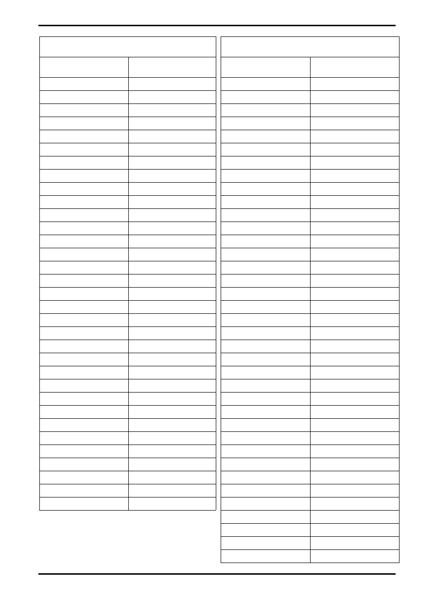
Relationship Between Temperature and Pressure
(R-134a Refrigerant)
Temperature Degrees C
(degrees F)
Pressure kPa (PSI)
−18 C (0.0 F)
44 kPa (6.4 PSI)
−17 C (2.0 F)
51 kPa (7.4 PSI)
−16 C (4.0 F)
59 kPa (8.5 PSI)
−14 C (6.0 F)
66 kPa (9.6 PSI)
−13 C (8.0 F)
74 kPa (10.7 PSI)
−12 C (10.0 F)
82 kPa (11.9 PSI)
−11 C (12.0 F)
90 kPa (13.1 PSI)
−10 C (14.0 F)
99 kPa (14.3 PSI)
−9 C (16.0 F)
108 kPa (15.6 PSI)
−8 C (18.0 F)
117 kPa (17.0 PSI)
−7 C (20.0 F)
127 kPa (18.4 PSI)
−6 C (21.0 F)
132 kPa (19.1 PSI)
−6 C (22.0 F)
137 kPa (19.8 PSI)
−5 C (23.0 F)
141 kPa (20.5 PSI)
−4 C (24.0 F)
147 kPa (21.3 PSI)
−4 C (25.0 F)
152 kPa (22.0 PSI)
−3 C (26.0 F)
157 kPa (22.8 PSI)
−3 C (27.0 F)
163 kPa (23.6 PSI)
−2 C (28.0 F)
168 kPa (24.4 PSI)
−2 C (29.0 F)
174 kPa (25.2 PSI)
−1 C (30.0 F)
179 kPa (26.0 PSI)
−1 C (31.0 F)
185 kPa (26.8 PSI)
0 C (32.0 F)
191 kPa (27.7 PSI)
1 C (33.0 F)
197 kPa (28.5 PSI)
1 C (34.0 F)
203 kPa (29.4 PSI)
2 C (35.0 F)
209 kPa (30.3 PSI)
2 C (36.0 F)
215 kPa (31.2 PSI)
3 C (37.0 F)
221 kPa (32.1 PSI)
3 C (38.0 F)
228 kPa (33.0 PSI)
4 C (39.0 F)
234 kPa (34.0 PSI)
4 C (40.0 F)
241 kPa (34.9 PSI)
5 C (41.0 F)
248 kPa (35.9 PSI)
6 C (42.0 F)
254 kPa (36.9 PSI)
Relationship Between Temperature and Pressure
(R-134a Refrigerant)
Temperature Degrees C
(degrees F)
Pressure kPa (PSI)
6 C (43.0 F)
261 kPa (37.9 PSI)
7 C (44.0 F)
263 kPa (38.9 PSI)
7 C (45.0 F)
275 kPa (39.9 PSI)
8 C (46.0 F)
283 kPa (41.0 PSI)
8 C (47.0 F)
290 kPa (42.0 PSI)
9 C (48.0 F)
297 kPa (43.1 PSI)
9 C (49.0 F)
305 kPa (44.2 PSI)
10 C (50.0 F)
312 kPa (45.3 PSI)
11 C (51.0 F)
320 kPa (46.4 PSI)
11 C (52.0 F)
328 kPa (47.5 PSI)
12 C (53.0 F)
336 kPa (48.7 PSI)
12 C (54.0 F)
344 kPa (49.9 PSI)
13 C (55.0 F)
352 kPa (51.0 PSI)
13 C (56.0 F)
360 kPa (52.2 PSI)
14 C (57.0 F)
369 kPa (53.5 PSI)
14 C (58.0 F)
377 kPa (54.7 PSI)
15 C (59.0 F)
385 kPa (55.9 PSI)
16 C (60.0 F)
394 kPa (57.2 PSI)
16 C (61.0 F)
403 kPa (58.2 PSI)
17 C (62.0 F)
412 kPa (59.8 PSI)
17 C (63.0 F)
421 kPa (61.1 PSI)
18 C (64.0 F)
430 kPa (62.4 PSI)
18 C (65.0 F)
440 kPa (63.8 PSI)
19 C (66.0 F)
450 kPa (65.2 PSI)
19 C (67.0 F)
459 kPa (66.8 PSI)
20 C (68.0 F)
469 kPa (68.0 PSI)
21 C (69.0 F)
478 kPa (69.4 PSI)
21 C (70.0 F)
488 kPa (70.8 PSI)
22 C (71.0 F)
498 kPa (72.3 PSI)
22 C (72.0 F)
509 kPa (73.8 PSI)
23 C (73.0 F)
519 kPa (75.3 PSI)
23 C (74.0 F)
530 kPa (76.8 PSI)
24 C (75.0 F)
540 kPa (78.3 PSI)
24 C (76.0 F)
551 kPa (79.9 PSI)
25 C (77.0 F)
562 kPa (81.5 PSI)
26 C (78.0 F)
573 kPa (83.1 PSI)
26 C (79.0 F)
584 kPa (84.7 PSI)