Scania ATSc Instrumentation en-GB 2 268 527. Operator's manual
Operator's manual
ATSc
Instrumentation
en-GB 2 268 527
Issue 1.0
Preface
3
Function
3
Instrument panel
4
Switch
4
Indicator lamps
5
Display with switches
6
Display
7
Layout
7
Navigation through the measured values for the
parameters
8
Alarm
10
Configuration mode
11
Testing the instrument panel
11
Test with load
11
Test without load
11
Components in the central electric unit
12
2
Preface
Preface
This Operator’s manual describes operation of ATSc instrument
panel.
The information in this manual was correct at the time of going
to press. Scania reserves the right to make alterations without pri-
or notice.
Note:
Always use Scania spare parts for repair work.
Function
The instrument panel for the automatic transfer switch (ATS) can
be used when a generator set is being used as a stand-by generator
set in an electrical consumer network. The instrument panel is lo-
cated in the switchgear of the electrical consumer network.
When the instrument panel detects a power failure in the electri-
cal power network, a signal is sent to the generator set requesting
it to start and take over the load from the electrical consumers.
When the instrument panel detects that the mains voltage is back
up, the generator set stops.
The display of the instrument panel indicates the voltages and
frequencies of each phase, the engine running time, the next in-
spection, the number of times the generator has been connected
and active alarm messages.
Indicator lamps show the current operating mode, the status of
the circuit breakers and the availability of mains voltage and gen-
erator voltage.
The instrument panel can be run in both automatic and manual
operating modes.
3

Instrument panel
Instrument panel
The figure below displays the instrument panel with switches, in-
dicator lamps and display.
V
Hz
h
1
2
18
3
7
9
10
11
8
13
14
16
12
17
15
1
STOP
6
2
3
4
5
Switch
Item
Switch
Function
Acknowledges active alarm messages and cancels the alarm signal. Indicator
lamp 14 goes out when there are no alarm messages.
2
Changes operating mode. In manual operating mode, indicator lamp 16 is on and
in automatic operating mode indicator lamp 15 is on. This switch is deactivated
3
when the operating mode has been selected externally.
Closes or opens the circuit breaker in the generator set and in the automatic trans-
fer switch respectively, depending on the current status of the circuit breakers.
4
This switch is only active in manual operating mode.
Starts the engine. This switch is only active in manual operating mode. If the in-
strument panel does not detect a generator voltage and frequency after
5
60 seconds, the Engine start failure alarm is triggered. This switch is deactivated
when the instrument panel is in automatic operating mode or when the operating
mode has been selected externally.
4

Instrument panel
Item
Switch
Function
Switches off the engine. This switch is always active. If the switch is pressed once
the engine is switched off following a cooling period. If the circuit breaker in the
STOP
generator set is closed and the circuit breaker in the automatic transfer switch is
6
open when the switch is pressed, the former opens while the latter is closed, if
there is mains voltage. If the switch is pressed twice the engine is switched off
immediately.
Indicator lamps
Item
Function
The indicator lamp is on when mains voltage is available and it is within the limits.
9
The indicator lamp flashes when mains voltage or frequency is not within limits.
10
The indicator lamp is on when the circuit breaker in the automatic transfer switch is closed.
11
The indicator lamp is on when the circuit breaker in the generator set is closed.
The indicator lamp is on when there is a generator voltage and frequency and they are with-
12
in limits.
The indicator lamp flashes when the generator voltage or frequency are not within limits.
The indicator lamp is on when the engine is running.
13
The indicator lamp flashes when the engine is running, but engine protection monitoring is
not ready. The indicator lamp also flashes when the engine is in its startup or cooling phase.
14
The indicator lamp is on when there are alarm messages.
15
The indicator lamp is on in automatic operating mode.
16
The indicator lamp is on in manual operating mode.
17
The indicator lamp is on when the generator set is stopped.
Note:
Press switches 7 and 8 at the same time to carry out a function test
of all indicator lamps and the display.
5

Instrument panel
Display with switches
Item
Switch
Function
1
Scroll to show the monitored parameters on the display. This
switch is active when the instrument panel is in normal operation.
7
Increase a value for the selected parameter when the instrument
panel is in configuration mode.
8
Decrease a value for the selected parameter when the instrument
panel is in configuration mode.
18
Alphanumeric display with 6 characters. Measured values, oper-
ating parameters and alarm messages are displayed here.
6

Display
Display
Layout
The display shows a number of numerical measured values dur-
ing operation.
4
5
6
7
3
1
2
2
3
1
8
Display with 6 characters
• The first character in the display (from the left) shows the unit
being measured: generator 1, automatic transfer switch 2 or
electrical power network 3.
• The second character in the display indicates the phase 8 be-
ing measured. The upper bar indicates L1, the central bar in-
dicates L2 and the lower bar indicates L3. If only one bar is
displayed the phase is being measured to neutral. If two bars
are displayed, phase to phase is being measured.
• Characters 3 to 6 indicate a numeric value with one decimal
for the displayed parameter.
• The indicator lamps located above to the left by the first 4
characters indicate the following:
- Indicator lamp 4 on displays the unit of measurement volt-
age (V).
- Indicator lamp 5 on displays the unit of measurement fre-
quency (Hz).
- Indicator lamp 6 on displays the number of running hours
(h).
- Indicator lamp 7 on displays the number of times the gen-
erator has been connected (n).
The example in the above figure shows that the generator voltage
is 235.0 V between phase L2 and neutral.
• The bar in the first character indicates the unit generator.
• The bar in the second character indicates the measurement be-
tween phase L2 and neutral.
• Characters 3 to 6 indicate the numerical value 235.0.
• Indicator lamp 4 on at the first character shows that the unit of
measurement is voltage (V).
7
Display
Navigation through the measured val-
ues for the parameters
With the instrument panel in normal operation the basic value is
always displayed first when the instrument panel evaluates the
measured voltage and the positions of the circuit breakers.
Press switch 1 to see the measured values of the parameters in the
following sequence.
Parameter
Display
Mains voltage V12 (VLine).
1
2
3
Mains voltage V23 (VLine).
1
2
3
Mains voltage V31 (VLine).
1
2
3
Mains voltage. Average of phase to phase
1
voltages (two of three indicator lamps for
2
phase are displayed alternately).
3
Mains voltage V1N (VPhase).
1
2
3
Mains voltage V2N (VPhase).
1
2
3
Mains voltage V3N (VPhase).
1
2
3
Mains voltage. Average of the phase voltag-
1
es (the three indicator lamps for phase are
2
displayed alternately).
3
Rated mains frequency.
1
2
3
Generator voltage V12 (VLine).
1
2
3
Generator voltage V23 (VLine).
1
2
3
8

Display
Parameter
Display
Generator voltage V31 (VLine).
1
2
3
Generator voltage. Average of phase to
1
phase voltages (two of three indicator lamps
2
for phase are displayed alternately).
3
Generator voltage V1N (VPhase).
1
2
3
Generator voltage V2N (VPhase).
1
2
3
Generator voltage V3N (VPhase).
1
2
3
Generator voltage. Average of the phase
1
voltages (the three indicator lamps for phase
2
are displayed alternately).
3
Rated generator frequency.
1
2
3
Engine running time counter in hours (six
1
digit display with one decimal).
2
3
Hour counter to next inspection (a negative
1
value indicates that the service due date has
2
been passed).
3
Counter for the number of times the genera-
1
tor has been connected.
2
3
Battery voltage
1
2
3
If switch 1 is pressed again the display returns to the basic value.
The display automatically returns to the basic value after 180 sec-
onds if no switch is pressed.
9

Display
Alarm
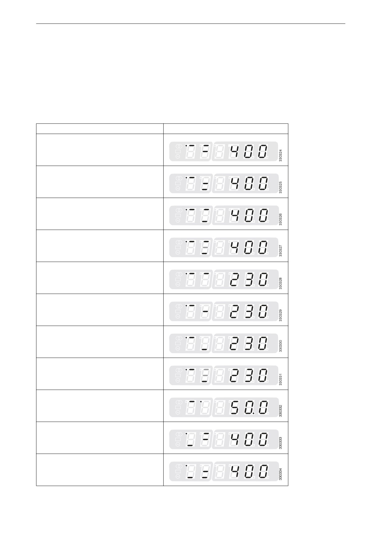
Alarm
Alarm class
Display
10
Generator overfrequency.
F Shutdown.
1
2
3
11
Generator underfrequency.
F Shutdown.
1
2
3
12
Generator overvoltage.
F Shutdown.
1
2
3
13
Generator undervoltage.
F Shutdown.
1
2
3
14
Incorrect phase rotation.
B Alarm.
1
2
3
30
Engine start failure.
F Shutdown.
1
2
3
31
Unintentional stop.
F Shutdown.
1
2
3
40
Time for inspection.
B Alarm.
1
2
3
51
Incorrect closing of the circuit
B Alarm.
1
breaker in the generator set.
2
3
52
Incorrect opening of the circuit
B Alarm.
1
breaker in the generator set.
2
3
53
Incorrect closing of the circuit
B Alarm.
1
breaker in the automatic trans-
2
fer switch.
3
54
Incorrect opening of the circuit
B Alarm.
1
breaker in the automatic trans-
2
fer switch.
3
10
Testing the instrument panel
Configuration mode
To go into configuration mode press switches 1 and 2 at the same
time.
The following parameters are displayed:
•
00 - Password
•
01 - Time to alarm signal reset
•
72 - Display level.
To display the other parameters, enter the password for parameter
00 - Password (0003).
Press switch 1 to scroll down among the parameters that can be
changed. Press switch 7 to increase the value of the selected pa-
rameter or press switch 8 to decrease the value.
Testing the instrument panel
Test with load
1. Press switch 3 to put the instrument panel in manual operat-
ing mode.
2. Press switch 5 to start the generator set engine.
3. When the frequency and voltage are within limits and indica-
tor lamps 12 and 13 have switched from flashing to steadily
lit, the circuit breaker in the automatic transfer switch can be
opened and the circuit breaker in the generator set closed by
pressing switch 4. This puts a load on the generator.
4. When the test with load is completed: return the load to the
electrical power network by opening the circuit breaker in the
generator set and closing the circuit breaker in the automatic
transfer switch. Stop the generator set by pressing switch 3.
This completes the test with load procedure and puts the in-
strument panel into automatic operating mode, in stand-by to
detect a power failure in the electrical power network.
Test without load
1. Press switch 3 to put the instrument panel in manual operat-
ing mode.
2. Press switch 5 to start the generator set engine.
3. When the test without load is completed, stop the generator
set by pressing switch 3. This completes the test without load
procedure and puts the instrument panel into automatic oper-
ating mode, in stand-by to detect a power failure in the elec-
trical power network.
11
Components in the central electric unit
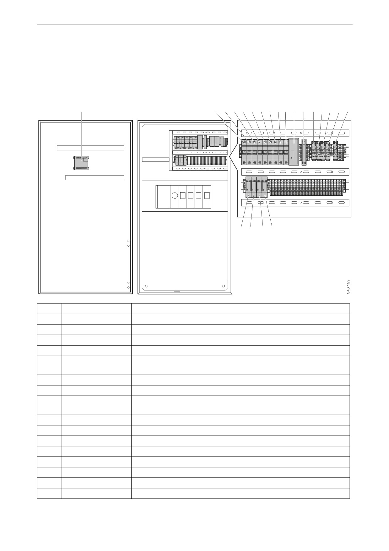
Components in the central electric
unit
The illustration below shows the location of the components in-
side the central electric unit.
1
2
3
4
5
6
7
8
9 10 11 12 13 14 15 16 17
18 19
20 21
Pos.
Designation
Description
1
ATSc
Instrument panel for an automatic transfer switch
2-4
F6-F4
Miniature circuit breakers for detecting mains voltage
5
F8
Miniature circuit breaker for network supply of 2-way power supply
6
F7
Miniature circuit breaker for external power supply
7
F9
Miniature circuit breaker for voltage supply from generator set to 2-way
power supply
8-10
F3-F1
Miniature circuit breakers for detecting voltage from generator set
11
2-way power supply
12
Direct current power
supply
13
GR1
Relay for supply from generator set
14
GAR
Relay for supply of external voltage to generator set
15
MAR
Relay for supply of external voltage
16
RSR
Relay for remote start
17
RSR2
Relay for remote start
18
MCRC
Circuit breaker closes
19
MCRO
Circuit breaker opens
20
GCR
Generator set switch closes
12

Components in the central electric unit
Pos.
Designation
Description
21
MCRAC
Circuit breaker closes automatically
13