Nissan Rogue (2023 year). Manual in english - page 13
3-24
Pre-driving checks and adjustments
WARNING
.
Make sure the hood is completely
closed and latched before driving.
Failure to do so could cause the
hood to fly open and result in an
accident.
.
Never open the hood if steam or
smoke is coming from the engine
compartment to avoid injury.
WAD0150X
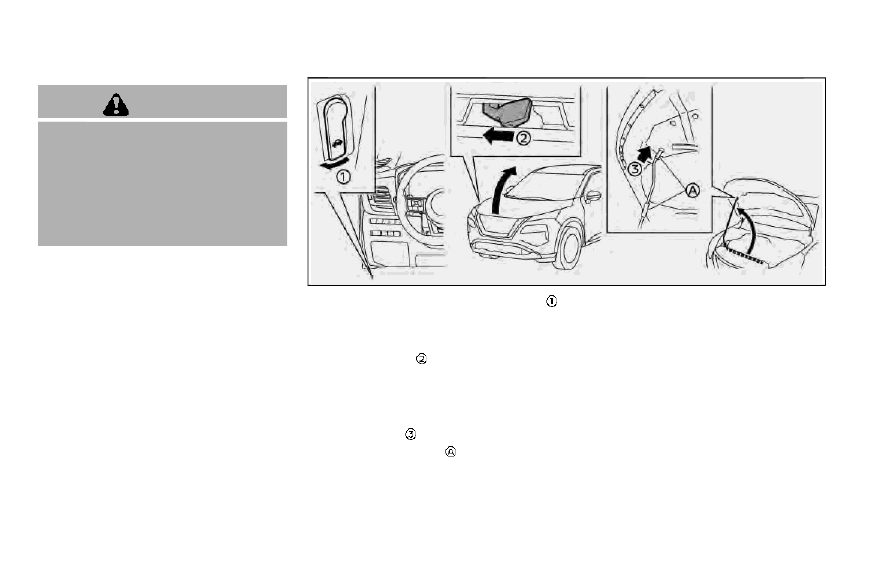
1.
Pull the hood lock release handle
located below the driver’s side instru-
ment panel; the hood springs up
slightly.
2.
Push the lever
underneath the front
of the hood sideways as illustrated
with your fingertips.
3.
Raise the hood.
4. Remove the support rod and insert it
into the slot
.
Hold the coated parts
when removing
or resetting the support rod. Avoid
direct contact with the metal parts, as
they may be hot immediately after the
engine has been stopped.
When closing the hood:
1.
While supporting the hood, return the
support rod to its original position.
2.
Slowly lower the hood to about 8 to 12
in (20 to 30 cm) above the hood lock,
then let it drop.
3.
Make sure it is securely latched.
HOOD