Nissan Titan (2023 year). Manual in english - page 15


  Index      Manuals     Nissan Titan (2023 year). Manual in english


Search            copyright infringement  


Content      ..     13      14      15      16     ..


Nissan Titan (2023 year). Manual in english - page 15


Loose Fuel Cap warning

The Loose Fuel Cap warning appears in the
vehicle information display when the fuel-
filler cap is not tightened correctly after the
vehicle has been refueled. It may take a few
driving trips for the message to be dis-
played. To turn off the warning, perform the
following:

1. Remove and install the fuel-filler cap as

previously

described

as

soon

as

possible.

2. Tighten the fuel-filler cap until a single

click is heard.

WARNING

Do not adjust the steering wheel
while driving. You could lose control
of

your

vehicle

and

cause

an

accident.

Do not adjust the steering wheel any
closer to you than is necessary for
proper steering operation and com-
fort. The driver's air bag inflates with
great force. If you are unrestrained,
leaning forward, sitting sideways or
out of position in any way, you are at
greater risk of injury or death in a
crash. You may also receive serious
or fatal injuries from the air bag if you
are up against it when it inflates. Al-
ways sit back against the seatback
and as far away as practical from the
steering wheel. Always use the seat
belts.

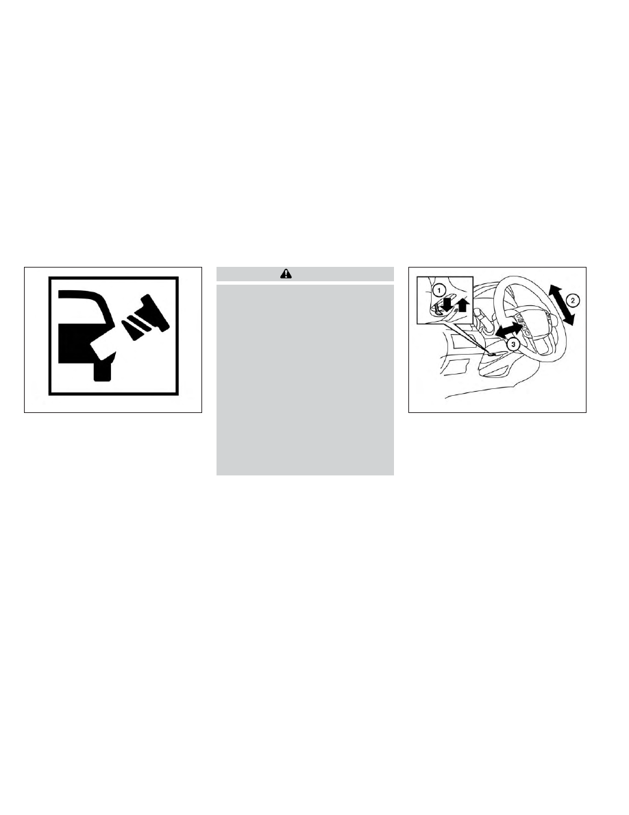
MANUAL OPERATION (if so
equipped)

Tilt and telescopic operation

Push the lock lever

O

1

down:

• Adjust the steering wheel up or down in

direction

O

2

to the desired position.

• Adjust the steering wheel forward or

backward in direction

O

3

to the desired

position.

Pull the lock lever

O

1

up firmly to lock the

steering wheel in place.

LPD2985

LPD2597

STEERING WHEEL

3-28

Pre-driving checks and adjustments

-------------------------------------------------------------------------------------------------------------------------------------------------------------

AUTOMATIC OPERATION (if so
equipped)

Tilt and telescopic operation

To adjust the steering wheel move the
switch

O

1

in the following directions:

• Adjust the steering wheel up or down in

direction

O

2

to the desired tilt position.

• Adjust the steering wheel forward or

backward in direction

O

3

to the desired

telescopic position.

CAUTION

For vehicles with Memory Seat: Failure
to reset the tilt and telescoping func-
tions of the steering wheel, after the
vehicle’s battery has been discharged,
may prevent the steering wheel posi-
tion from being adjusted.

For vehicles with Memory Seat: Both the tilt
and telescopic steering operation must be
reset after the vehicle’s battery has been
discharged in order to prevent the tilt and
telescopic operation from locking in one
position. When the battery has been re-
charged or replaced, perform the following:
• For tilt operation: Adjust the switch

O

1

so

the steering wheel moves to the highest
position

O

2

that can be reached.

• For

telescopic

operation: Adjust

the

switch

O

1

so the steering wheel moves to

the most forward and backward position

O

3

that can be reached.

Performing these operations resets the
range of the steering wheel’s tilt and tele-
scopic function.

Entry/Exit function (if so
equipped)

The memory seat will make the steering
wheel move up automatically when the
driver's door is opened and the ignition
switch is in the LOCK position. This lets the
driver get into and out of the seat more
easily. The steering wheel moves back into
position when the driver's door is closed
and the ignition switch is pushed.

For additional information, see “Memory
seat” (P. 3-41).

LPD2580

Pre-driving checks and adjustments

3-29

-------------------------------------------------------------------------------------------------------------------------------------------------------------

1. To block glare from the front, swing

down

O

1

the sun visor.

2. To block glare from the side, remove the

sun visor from the center mount and
swing the visor to the side

O

2

.

3. To extend the sun visor, slide

O

3

in or out

as needed.

CAUTION

Do not store the sun visor before re-
turning the extension to its original
position.

Do not pull the extension sun visor
forcedly downward.

VANITY MIRRORS (if so equipped)

To access the vanity mirror, pull the sun
visor down and flip open the mirror cover.
Some vanity mirrors are illuminated and
turn on when the mirror cover is open.

WPD0344

LPD2583

SUN VISORS

3-30

Pre-driving checks and adjustments

-------------------------------------------------------------------------------------------------------------------------------------------------------------

CARD HOLDER (driver’s side only)

To access the card holder, slide card in the
card holder. Do not view information while
operating the vehicle.

MANUAL ANTI-GLARE REARVIEW
MIRROR (if so equipped)

Use the night position

O

1

to reduce glare

from the headlights of vehicles behind you
at night.

Use the day position

O

2

when driving in

daylight hours.

WARNING

Use the night position only when nec-
essary, because it reduces rear view
clarity.

AUTOMATIC ANTI-GLARE
REARVIEW MIRROR (if so equipped)

The inside mirror is designed so that it au-
tomatically dims during nighttime condi-
tions and according to the intensity of the
headlights of the vehicle following you. The
automatic anti-glare feature is activated
when the ignition switch is in the ON
position.

NOTE:

Do not hang any objects over the sen-
sors

O

1

or apply glass cleaner to the sen-

sors. Doing so will reduce the sensitivity
of the sensors, resulting in improper
operation.

LPD2436

WPD0126

MIRRORS

Pre-driving checks and adjustments

3-31

-------------------------------------------------------------------------------------------------------------------------------------------------------------

Type A (if so equipped)

The inside mirror is designed so that it au-
tomatically dims during night time condi-
tions and according to the intensity of the
headlights of the vehicle following you. The
automatic anti-glare feature is activated
when the ignition switch is in the ON
position.

NOTE:

Do not hang any objects over the sen-
sors

O

1

or apply glass cleaner to the sen-

sors. Doing so will reduce the sensitivity
of the sensors, resulting in improper
operation.

Type B (if so equipped)

The indicator light

O

2

will illuminate when

the automatic anti-glare feature is operat-
ing.
• To turn off the automatic anti-glare fea-

ture, press the

O

button. The indicator

light will turn off.

• To turn on the automatic anti-glare fea-

ture, press the

|

button again. The in-

dicator light will turn on.

For additional information on HomeLink®
Universal

Transceiver

operation,

see

“HomeLink® Universal Transceiver (Type A)”
(P. 2-92).

NOTE:

Do not hang any objects over the sen-
sors

O

1

or apply glass cleaner to the sen-

sors. Doing so will reduce the sensitivity
of the sensors, resulting in improper
operation.

LPD2418

LPD0469

3-32

Pre-driving checks and adjustments

-------------------------------------------------------------------------------------------------------------------------------------------------------------

Type C (if so equipped)

The inside mirror is designed so that it au-
tomatically dims during nighttime condi-
tions and according to the intensity of the
headlights of the vehicle following you. The
automatic anti-glare feature is activated
when the ignition switch is in the ON
position.

For additional information on HomeLink®
Universal

Transceiver

operation,

see

“HomeLink® Universal Transceiver (Type B)”
(P. 2-97).

NOTE:

Do not hang any objects over the sen-
sors

O

1

or apply glass cleaner to the sen-

sors. Doing so will reduce the sensitivity
of the sensors, resulting in improper
operation.

OUTSIDE MIRRORS

WARNING

Objects viewed in the outside mirror
on the passenger side are closer than
they appear. Be careful when moving
to the right. Using only this mirror
could cause an accident. Use the in-
side mirror or glance over your
shoulder to properly judge distances
to other objects.

Do not adjust the mirrors while driv-
ing. You could lose control of your ve-
hicle and cause an accident.

Manual control type (if so
equipped)

The outside mirrors can be moved in any
direction for a better rear view.

LPD3366

LPD2581

Pre-driving checks and adjustments

3-33

-------------------------------------------------------------------------------------------------------------------------------------------------------------

Electric control type (if so
equipped)

The outside mirror control switch will oper-
ate only when the ignition switch is placed
in the ACC or ON position.

Rotate the control dial to select the right or
left mirror. Adjust the mirror to the desired
position by moving the control dial.

Return the control dial to the center (neu-
tral) position to prevent accidentally mov-
ing the mirror.

Trailer tow mirrors (if so equipped)

WARNING

Objects viewed in the convex portion of
the trailer tow mirror are closer than
they appear. Be careful when changing
lanes or turning. Using only the convex
mirror could cause an accident. Use the
other mirrors or glance over your
shoulder to properly judge distances to
other objects.

Use the outside mirror control switch to
adjust the top portion of the trailer tow
mirror.

The lower portion of the trailer tow mirror
can be moved manually in any direction for
a better rear view.

LPD2606

LPD2474

3-34

Pre-driving checks and adjustments

-------------------------------------------------------------------------------------------------------------------------------------------------------------

Pull the trailer tow mirror outward to ex-
tend it to the desired position for better
visibility while towing a trailer.

WARNING

Do not extend or retract mirrors while
driving. You may lose control of your
vehicle and cause an accident.

CAUTION

Driving in tight spaces with mirrors ex-
tended may cause damage to the
vehicle.

Manual folding outside mirrors (if
so equipped)

Pull the outside mirror toward the door to
fold it.

LPD0268

LPD3102

Type A (if so equipped)

LPD0269

Type B (if so equipped)

Pre-driving checks and adjustments

3-35

-------------------------------------------------------------------------------------------------------------------------------------------------------------

Power folding outside mirrors (if
so equipped)

CAUTION

Do not manually fold the power folding
mirrors. Manually folding the mirrors
can damage the mirrors.

Push the power folding switch to open or
close the mirrors.

If one of the mirrors are manually operated
or bumped, the mirror body can become
loose at the pivot point. To correct elec-
tronic mirror operation, cycle the mirrors by

pushing the power folding switch until the
mirrors are in the open position.

Reverse tilt-down feature (if so
equipped)

The reverse tilt-down feature will turn both
outside mirror surfaces downward to pro-
vide better rear visibility close to the vehicle
when the mirror control switch is in either
the L or R position.

The mirrors automatically return to their
original position when you shift out of R
(Reverse).

The outside mirror surfaces will return to
their original position when one of the fol-
lowing conditions has occurred:
• The shift lever is moved to any position

other than R (Reverse).

• The outside mirror control switch is set to

the neutral or center position.

• The ignition switch is placed in the OFF

position.

NOTE:

If the outside mirror control switch is in
the center position, the mirror surface
will NOT turn downward when the shift
lever is moved to R (Reverse).

For additional information, see “Memory
seat” (P. 3-41).

Automatic anti-glare outside
mirror (if so equipped)

The outside mirror will automatically dim
during nighttime conditions to reduce the
glare from the headlights of trailing ve-
hicles. The automatic anti-glare feature
operates only when the ignition switch is
placed in the ON position.

The automatic anti-glare feature will be on
when starting the vehicle. The indicator
light (if so equipped) on the automatic anti-
glare rearview mirror will illuminate when
the

automatic

anti-glare

feature

is

operating.

For additional information on the auto-
matic anti-glare rearview mirror, see “Auto-
matic anti-glare rearview mirror (if so
equipped)” (P. 3-31).

Heated mirrors (if so equipped)

Some outside mirrors can be heated to
defrost, defog, or de-ice for improved vis-
ibility. For additional information, see “Rear
window and/or outside mirror defroster
switch” (P. 2-45).

LPD0417

3-36

Pre-driving checks and adjustments

-------------------------------------------------------------------------------------------------------------------------------------------------------------

TAILGATE

Opening the tailgate

Pull the tailgate handle upward and lower
the tailgate. The support cables hold the
tailgate open.

When closing the tailgate, make sure the
latches are securely locked.

Do not drive the vehicle with the tailgate
down, unless equipped with NISSAN's
Bed Extender (accessory) or equivalent
in the extended position.

For additional information on proper truck
box loading, see “Vehicle loading informa-
tion” (P. 10-20).

WARNING

Never allow anyone to ride in the
cargo area or on the rear seat (if so
equipped) when it is in the folded po-
sition. Use of these areas by passen-
gers without proper restraints could
result in serious injury or death in an
accident or sudden stop.

It is extremely dangerous to ride in a
cargo area inside a vehicle. In a colli-
sion, people riding in these areas are
more likely to be seriously injured or
killed.

Do not allow people to ride in any
area of your vehicle that is not
equipped with seats and seat belts.

Be sure everyone in your vehicle is in
a seat and using a seat belt properly.

LPD3103

TRUCK BOX

Pre-driving checks and adjustments

3-37

-------------------------------------------------------------------------------------------------------------------------------------------------------------

Disconnecting the rear camera

Before removing the tailgate disconnect
the rear camera by performing the follow-
ing:

1. Open the tailgate to access the rear

camera connector bracket

O

1

located

on the rear sill.

2. Remove the connector bracket

O

2

from

the sill by pressing the locking tab in-
ward, in the direction shown, while pull-
ing the bracket apart.

3. Disconnect the chassis wiring harness

O

3

by pressing inward on the locking

tab, in the direction shown, while pulling
the connectors apart. Hold the connec-
tor firmly to prevent the connector in the
chassis harness from falling into the sill.

4. Use the supplied chassis plug and

bracket and connect them to the chas-
sis wiring harness to avoid contamina-
tion to the terminals which will lead to
malfunction of the rear camera.

5. Insert the bracket back into the sill.

6. Take the tailgate plug from the glove box

and connect it to the tailgate wiring har-
ness to avoid contamination which will
lead to malfunction of the rear camera.

7. Remove the tailgate. For additional infor-

mation, see “Removing the tailgate”
(P. 3-39).

LPD3095

3-38

Pre-driving checks and adjustments

-------------------------------------------------------------------------------------------------------------------------------------------------------------

Removing the tailgate

1. Disconnect the wiring harness for the

rear camera. For additional information,
see “Disconnecting the rear camera”
(P. 3-38).

2. Release the tailgate support cables.

CAUTION

The tailgate is heavy. Two people
should remove or install it. Be careful
not to drop it during removal.

After releasing the support cables,
do not let the tailgate rest on the
bumper.

3. Hold the tailgate at a 45 degree angle.

4. Pull the tailgate out from the left side

hinge.

5. Slide the tailgate out of the right side

hinge.

Installing the tailgate

1. Insert the tailgate into the right side

hinge.

2. Hold the tailgate at a 45 degree angle

and insert into the left side hinge.

3. Continue to hold the tailgate at a 45 de-

gree angle and attach the tailgate sup-
port cables.

4. For vehicles with rear camera: Be sure

the tailgate harness is not hanging be-
low the tailgate and keep the tailgate
open. For additional information, see
“Connecting the rear camera” (P. 3-40).

5. For vehicles without rear camera: Close

the tailgate securely.

LPD3104

Pre-driving checks and adjustments

3-39

-------------------------------------------------------------------------------------------------------------------------------------------------------------

Connecting the rear camera

Before closing the tailgate reconnect the
rear camera by performing the following:

1. After attaching the rear tailgate to the

truck, keep the tailgate open and check
that the tailgate harness is not hanging
below the tailgate.

2. Remove the connector bracket

O

2

from

the sill by pressing the locking tab in-
ward, in the direction shown, while pull-
ing the bracket apart.

3. Disconnect

the

chassis

plug

and

bracket from the chassis wiring harness

O

3

. Keep the connector and bracket in a

safe place such as the glove box.

4. Disconnect the tailgate plug from the

tailgate wiring harness. Keep the tail-
gate plug in a safe place such as the
glove box.

5. Connect the tailgate wiring harness to

the chassis wiring harness.

6. Securely fix the rear camera connector

bracket

O

1

to the rear sill.

7. Close the tailgate securely.

Locking the Tailgate

To unlock the tailgate, turn the key toward
the passenger side of the vehicle

O

1

. To

lock, turn the key toward the driver side

O

2

.

If your vehicle is equipped with an elec-
tronic locking tailgate (if so equipped), you
may use the door handle request switch (if
so equipped) or I-key to lock or unlock the
tailgate. For additional information please
see “NISSAN Intelligent Key® Operation”
(P. 3-12).

LPD3095

LPD3128

3-40

Pre-driving checks and adjustments

-------------------------------------------------------------------------------------------------------------------------------------------------------------

TIE DOWN HOOKS

For your convenience, tie down hooks are
placed at each corner of the truck box.
These may be used to help secure cargo
loaded into the truck box.
• The weight of the cargo load must be

evenly distributed over the rear axles.

• All cargo should be securely fastened

with ropes or straps to prevent it from
shifting or sliding within the vehicle.

WARNING

Properly secure all cargo with ropes
or straps to help prevent it from slid-
ing or shifting. In a sudden stop or
collision,

unsecured

cargo

could

cause personal injury.

The

memory

seat

system

has

two

features:
• Memory storage function
• Entry/exit function

LPD3105

MEMORY SEAT (if so equipped)

Pre-driving checks and adjustments

3-41

-------------------------------------------------------------------------------------------------------------------------------------------------------------

MEMORY STORAGE FUNCTION

Two positions for the driver's seat, steering
column,

and

outside

mirrors

(if

so

equipped) can be stored in the memory
seat system. Follow these procedures to
set the memory system.

1. Place the ignition in the ON or ACC posi-

tion (the vehicle should be stopped while
setting the memory).

2. Adjust the driver's seat, steering column,

and outside mirrors (if so equipped) to
the desired positions by manually oper-
ating each adjusting switch. For addi-
tional information, see “Seats” (P. 1-2),
“Steering wheel” (P. 3-28) and “Outside
mirrors” (P. 3-33).

3. Push the SET switch and, within 5 sec-

onds, push the memory switch (1 or 2).

4. The indicator light for the pushed

memory switch will come on and stay
on for approximately 5 seconds.

5. The chime will sound when the memory

is stored.

NOTE:

If a NEW memory position is stored in the
same memory switch, the previous
memory position will be overwritten by
the new stored position.

Confirming memory storage

• Push the SET switch.
• If a memory position has been stored in

the switch (1 or 2) then the indicator light
for the respective switch will stay on for
approximately 5 seconds.

Linking a key fob to a stored
memory position (if so equipped)

Each key fob can be linked to a stored
memory position (memory switch 1 or 2)
with the following procedure.

1. Follow steps 1-3 in the “Memory storage

function” section for storing the memory
position.

2. The indicator light for the pushed

memory switch will come on. While the
indicator light is on for 5 seconds, press
the

button on the key fob. The haz-

ard lights will flash once. The indicator
light of the linked memory switch will
blink and click twice. After the indicator
light goes off, the key fob is linked to that
memory setting.

Once it is linked, when the ignition switch is
in the OFF position, pressing the

but-

ton on the key fob will move the driver’s
seat, steering wheel and outside mirrors to
the linked memory switch position.

NOTE:

If a new memory position is stored in the
linked memory switch, then the key fob
will link the new position and overwrites
the previous position.

LPD2302

3-42

Pre-driving checks and adjustments

-------------------------------------------------------------------------------------------------------------------------------------------------------------

ENTRY/EXIT FUNCTION

This system is designed so that the driver's
seat and steering column will automati-
cally move when the shift lever is in the P
(Park) position. This allows the driver to
easily get in and out of the driver’s seat.

The driver’s seat will slide backward and
the steering column will move up:
• When the driver’s door is opened with the

ignition switch in the OFF position.

• When the ignition switch is changed from

ACC to OFF with the driver’s door open.

The driver’s seat and steering wheel will
return to the previous position:
• When the ignition switch is changed from

ACC or ON while the shift lever is in the P
(Park) position.

The entry/exit function can be adjusted or
canceled through the vehicle settings in
the vehicle information display by perform-
ing the following:
• Switch the Exit Seat Slide from ON to OFF.
• Switch the Exit Steering UP from ON to

OFF.

Restarting the entry/exit function

If the battery cable is disconnected, or if the
fuse opens, the stored memory positions
will be lost and some of the functions will
be restricted:

1. Drive the vehicle over 25 mph (40 km/h).

OR

2. Open and close the driver's door more

than two times with the ignition switch
in the OFF position.

The entry/exit function should now work
properly.

SYSTEM OPERATION

The memory seat system will not work or
will stop operating under the following
conditions:
• When the vehicle speed is above 4 mph (7

km/h).

• When any of the memory switches are

pushed while the memory seat system is
operating.

• When the switch for the driver’s seat and

steering column is pushed while the
memory seat system is operating.

• When the seat has already been moved

to the memorized position.

• When no seat position is stored in the

memory switch.

• When the shift lever is moved from P

(Park) to any other position.

The memory seat system can be adjusted
and canceled. It is recommended you visit
a NISSAN dealer for this service.

Pre-driving checks and adjustments

3-43

-------------------------------------------------------------------------------------------------------------------------------------------------------------


Content      ..     13      14      15      16     ..