Nissan Titan (2023 year). Manual in english - page 10


  Index      Manuals     Nissan Titan (2023 year). Manual in english


Search            copyright infringement  


Content      ..     8      9      10      11     ..


Nissan Titan (2023 year). Manual in english - page 10


The movement and direction of
the oncoming vehicle and the
leading vehicle.

When only one light on the on-
coming vehicle or the leading ve-
hicle is illuminated.

When the oncoming vehicle or the
leading vehicle is a two-wheeled
vehicle.

Road conditions (incline, curve,
the road surface, etc.).

The number of passengers and
the amount of luggage.

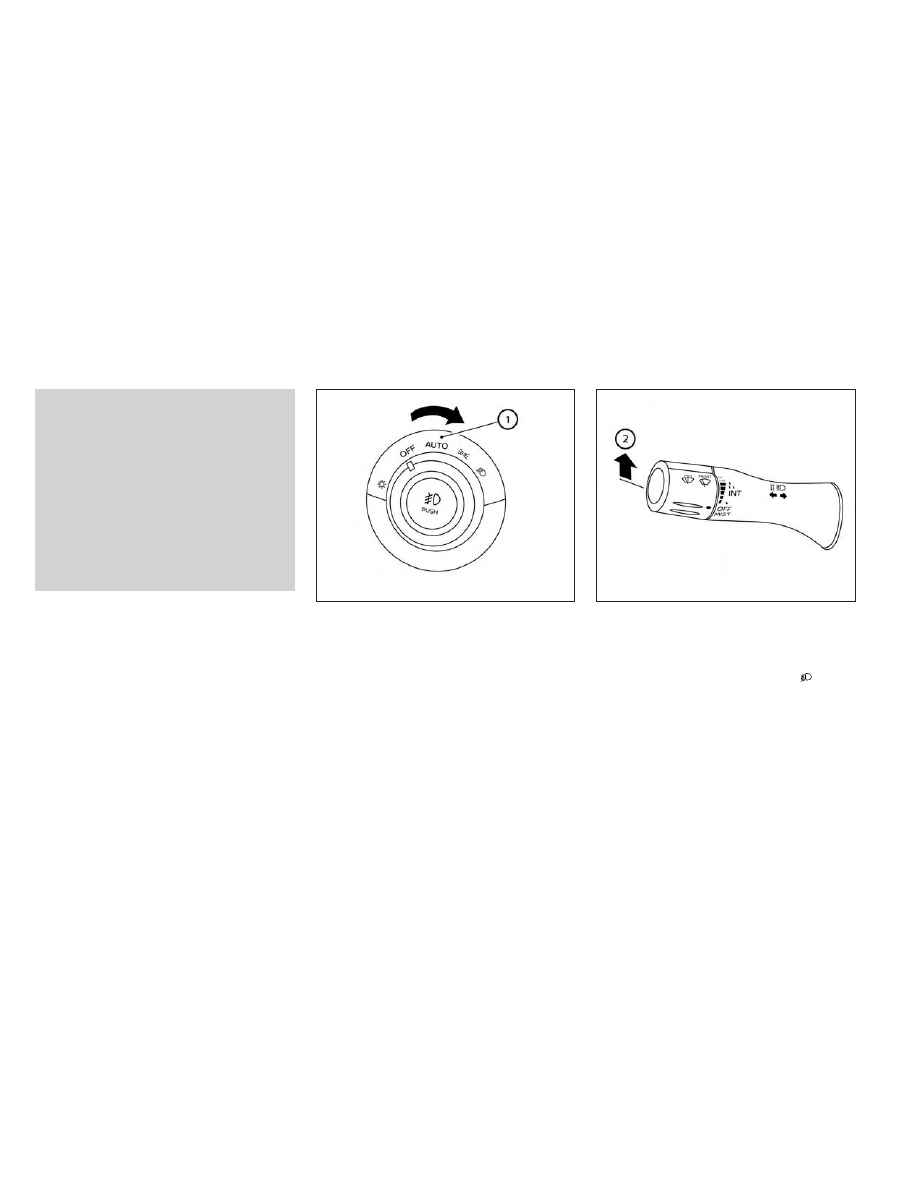
High Beam Assist operation

To activate the High Beam Assist system,
turn the headlight switch to the AUTO po-
sition

O

1

and then push the wiper and

washer switch forward

O

2

(high beam po-

sition). The High Beam Assist indicator light
in the meter will illuminate while the head-
lights are turned on.

If the High Beam Assist indicator light does
not illuminate in the above condition, it may
indicate that the system is not functioning
properly. Have the system checked, it is
recommended that you visit a NISSAN
dealer for this service.

When the vehicle speed lowers to less than
approximately 16 mph (25 km/h), the head-
light uses the low beam.

To turn off the High Beam Assist system,
turn the headlight switch to the

posi-

tion or select the low beam position by
placing the lever in the neutral position.

LIC4324

LIC4333

Instruments and controls

2-49

-------------------------------------------------------------------------------------------------------------------------------------------------------------

Ambient image sensor maintenance

The ambient image sensor

O

1

for the High

Beam Assist system is located in front of
the inside mirror. To maintain the proper
operation of the high beam assist system
and prevent a system malfunction, be sure
to observe the following:
• Always keep the windshield clean.
• Do not attach a sticker (including trans-

parent material) or install an accessory
near the ambient image sensor.

• Do not strike or damage the areas

around the ambient image sensor. Do
not touch the sensor lens that is located
on the ambient image sensor.

If the ambient image sensor is damaged
due to an accident, it is recommended that
you visit a NISSAN dealer.

Battery saver system

If the ignition switch is placed in the OFF
position while the headlight switch is in the

or

position, the headlights will

turn off after a period of time.

After the headlights automatically turn off
with the headlight switch in the

or

position, the headlights will illuminate

again if the headlight switch is moved to
the OFF position and then turned to the

or

position.

CAUTION

Even though the battery saver feature
automatically turns off the headlights
after a period of time, you should turn
the headlight switch to the OFF posi-
tion when the engine is not running to
avoid discharging the vehicle battery.

Manual headlight aiming control
(if so equipped)

Depending on the number of occupants in
the vehicle and the load it is carrying, the
headlight axis may be higher than desired.
If the vehicle is traveling on a hilly road, the
headlights may directly hit the rearview
mirror of the vehicle ahead or the wind-
shield of the oncoming vehicle. The light
axis can be lowered with the operation of
the switch.

The larger the number designated on the
switch, the lower the axis.

LSD2712

LIC2230

2-50

Instruments and controls

-------------------------------------------------------------------------------------------------------------------------------------------------------------

When traveling without a heavy load or on a
flat road, select position 0.

Select the switch position by referring to
the following sample.

Vehicle Load

Switch

Position

Driver only or Driver/front

passenger

0

Driver/front seat

passenger/rear seat pas-

sengers

1

Driver/front seat

passenger/rear seat

passengers/cargo or

driver/cargo/no trailer

2

Fully loaded/no trailer

3

LED DAYTIME RUNNING LIGHTS
(DRL) SYSTEM (if so equipped)

The LED portion of the headlights auto-
matically illuminates at 100% intensity
when the engine is started and the parking
brake released. The LED Daytime Running
Lights (LED DRL) operate with the headlight
switch in the OFF or AUTO position. When
you turn the headlight switch to the
position for full illumination, the LED lights
switch from LED DRL to the park function.

If the parking brake is applied before the
engine is started, the LED DRL do not illumi-
nate. The LED DRL illuminate when the
parking brake is released. The LED DRL re-
main on while the engine is running.

It is necessary at dusk to turn the headlight
switch

ON

for

interior

controls

and

switches to illuminate, as those remain off
while the switch is in the OFF position.

WARNING

When the LED DRL system is active, tail
lights on your vehicle are not on. It is
necessary at dusk to turn on your
headlights. Failure to do so could cause
an

accident

injuring

yourself

and

others.

INSTRUMENT BRIGHTNESS
CONTROL

Press the “+” button to increase the bright-
ness of instrument panel lights.

Press the “-” button to decrease the bright-
ness of instrument panel lights.

LIC3176

Instruments and controls

2-51

-------------------------------------------------------------------------------------------------------------------------------------------------------------

TURN SIGNAL SWITCH

Turn signal

1

Move the lever up or down to signal the
turning direction. When the turn is com-
pleted,

the

turn

signal

cancels

automatically.

Lane change signal

2

Move the lever up or down until the turn
signal begins to flash, but the lever
does not latch, to signal a lane change.
Hold the lever until the lane change is
completed.

Move the lever up or down until the turn
signal begins to flash, but the lever does
not latch, and release the lever. The turn
signal will automatically flash three times.

Choose the appropriate method to signal
a lane change based on road and traffic
conditions.

NOTE:

The 3 flash pass turn indicator may be
disabled. For additional information, see
“Vehicle information display” (P. 2-24).

To turn the fog lights on, turn the headlight
switch to the

position, then push the

fog light switch

O

1

on.

To turn the fog lights on with the headlight
switch in the AUTO position, the headlights
must be on, then push the fog light switch
on.

To turn the fog lights off, push the fog light
switch again.

The headlights must be on and the low
beams selected for the fog lights to oper-
ate. The fog lights automatically turn off
when the high beam headlights are
selected.

LIC3061

LIC4325

FOG LIGHT SWITCH (if so equipped)

2-52

Instruments and controls

-------------------------------------------------------------------------------------------------------------------------------------------------------------

Fog may temporarily form inside the lens
of the exterior lights in the rain or in a car
wash. A temperature difference between
the inside and the outside of the lens
causes fog. This is not a malfunction, if
large drops of water collect inside the lens,
it is recommended that you visit a NISSAN
dealer for servicing.

To sound the horn, push near the horn icon
on the steering wheel.

WARNING

Do not disassemble the horn. Doing so
could affect proper operation of the
supplemental front air bag system.
Tampering

with

the

supplemental

front air bag system may result in seri-
ous personal injury.

To turn on the cargo lamp and the under
rail bed lamps (if so equipped) push the
switch down to the ON position. The tail-
gate lights (if so equipped) will also illumi-
nate when the cargo lamp switch is in the
ON position.

CAUTION

Do not use for extended periods of time
with the engine stopped. This could re-
sult in a discharged battery.

LIC2051

LIC0616

HORN

CARGO LAMP SWITCH

Instruments and controls

2-53

-------------------------------------------------------------------------------------------------------------------------------------------------------------

WARNING

Do not use or allow occupants to use
the climate controlled seats if you or
the occupants cannot monitor seat
temperatures or have an inability to
feel pain in those body parts in contact
with the seat. Use of the climate con-
trolled seats by such people could re-
sult in serious injury.

CAUTION

The battery could run down if the cli-
mate control seat is operated while
the engine is not running.

Do not use the climate control seat
for extended periods or when no one
is using the seat.

Do not put anything on the seat
which insulates heat, such as a blan-
ket, cushion, seat cover, etc. Other-
wise,

the

seat

may

become

overheated.

Do not place anything hard or heavy
on the seat or pierce it with a pin or
similar objects. This may result in
damage to the climate controlled
seat.

Any liquid spilled on the seat should
be removed immediately with a dry
cloth.

The climate controlled seat has an air
filter. Do not operate the climate con-
trolled seat without an air filter. This
may result in damage to the system.

When cleaning the seat, never use
gasoline, benzine, thinner, or any
similar materials.

If any malfunctions are found or the
climate controlled seat does not op-
erate, turn the switch off and have
the system checked. It is recom-
mended that you visit a NISSAN
dealer for this service.

The climate controlled seat warms up or
cools down the front seat by blowing warm
or cool air from under the surface of the
seat. The climate control switch is located
on the center console.

The climate controlled seat can be oper-
ated as follows:

1. Start the engine.

2. Turn the control knob

O

A

to the heat side

O

1

or the cool side

O

2

. The indicator light

O

B

on the control knob will illuminate.

SIC4334

CLIMATE CONTROLLED SEAT
SWITCHES (if so equipped)

2-54

Instruments and controls

-------------------------------------------------------------------------------------------------------------------------------------------------------------

3. Adjust the desired amount of air using

the control knob. The climate controlled
seat blower remains on low speed for
approximately 60 seconds after turning
the switch on or selecting the desired
temperature.

4. When the vehicle's interior is warmed or

cooled, or before you leave the vehicle,
be sure to turn the control knob to the
Off (center) position. The indicator light

O

B

on the control knob goes off with the

switch in the off (center) position.

To check the air filter for the climate con-
trolled seat, it is recommended that you
contact a NISSAN dealer.

WARNING

Do not use or allow occupants to use
the seat heater if you or the occupants
cannot monitor elevated seat tem-
peratures or have an inability to feel
pain in body parts that contact the
seat. Use of the seat heater by such
people could result in serious injury.

CAUTION

Do not use the seat heater for ex-
tended periods or when no one is us-
ing the seat.

Do not put anything on the seat
which insulates heat, such as a blan-
ket, cushion, seat cover, etc. Other-
wise,

the

seat

may

become

overheated.

Do not place anything hard or heavy
on the seat or pierce it with a pin or
similar object. This may result in
damage to the heater.

Any liquid spilled on the heated seat
should be removed immediately with
a dry cloth.

When cleaning the seat, never use
gasoline, benzine, thinner, or any
similar materials.

If any malfunctions are found or the
heated seat does not operate, turn
the switch off and have the system
checked. It is recommended that you
visit a NISSAN dealer for this service.

The battery could run down if the
seat heater is operated while the en-
gine is not running.

HEATED SEAT SWITCHES (if so
equipped)

Instruments and controls

2-55

-------------------------------------------------------------------------------------------------------------------------------------------------------------

1. Start the engine.

2. Push the LO or HI position of the switch,

as desired, depending on the tempera-
ture. The indicator light in the switch will
illuminate.

The heater is controlled by a thermostat,
automatically turning the heater on and
off. The indicator light will remain on as
long as the switch is on.

3. When the seat is warmed or before you

leave the vehicle, be sure to turn the
switch off.

WARNING

Do not use or allow occupants to use
the seat heater if you or the occupants
cannot monitor elevated seat tem-
peratures or have an inability to feel
pain in body parts that contact the
seat. Use of the seat heater by such
people could result in serious injury.

CAUTION

The battery could run down if the
seat heater is operated while the en-
gine is not running.

Do not use the seat heater for ex-
tended periods or when no one is us-
ing the seat.

Do not put anything on the seat
which insulates heat, such as a blan-
ket, cushion, seat cover, etc. Other-
wise,

the

seat

may

become

overheated.

Do not place anything hard or heavy
on the seat or pierce it with a pin or
similar object. This may result in
damage to the heater.

Any liquid spilled on the heated seat
should be removed immediately with
a dry cloth.

When cleaning the seat, never use
gasoline, benzine, thinner, or any
similar materials.

If any malfunctions are found or the
heated seat does not operate, turn
the switch off and have the system
checked. It is recommended that you
visit a NISSAN dealer for this service.

LIC3037

HEATED REAR SEAT SWITCHES (if so
equipped)

2-56

Instruments and controls

-------------------------------------------------------------------------------------------------------------------------------------------------------------

The rear seats are warmed by built-in heat-
ers. The switches are located on the rear of
the front center console and can be oper-
ated independently of each other.

1. Start the engine.

2. Push the LO or HI position of the switch,

as desired. The indicator light in the
switch will illuminate.

The heater is controlled by a thermostat,
automatically turning the heater on and
off. The indicator light will remain on as
long as the switch is on.

3. When the seat is warmed or before you

leave the vehicle, be sure to turn the
switch off.

The heated steering wheel system is de-
signed to operate only when the surface
temperature of the steering wheel is below
68°F (20°C).

Push the heated steering wheel switch to
warm the steering wheel after the engine
starts. The indicator light will come on.

If the surface temperature of the steering
wheel is below 68°F (20°C), the system will
heat the steering wheel and cycle off and
on to maintain a temperature above 68°F
(20°C). The indicator light will remain on as
long as the system is on.

LIC3037

LIC4582

HEATED STEERING WHEEL SWITCH (if
so equipped)

Instruments and controls

2-57

-------------------------------------------------------------------------------------------------------------------------------------------------------------

Push the switch again to turn the heated
steering wheel system off manually. The
indicator light will go off. The switch will turn
off automatically 30 minutes after activa-
tion, once this happens the switch will need
to be pressed again to restart the cycle.

NOTE:

If the surface temperature of the steer-
ing wheel is above 68°F (20°C) when the
switch is turned on, the system will not
heat the steering wheel. This is not a
malfunction.

The warning systems switch is used to turn
on and off the following systems that are
activated using the Settings menu in the
vehicle information display:
• Blind Spot Warning (BSW)
• Lane Departure Warning (LDW)

When the warning systems switch is
turned off, the indicator

O

1

on the switch is

off. The indicator will also be off if all of the
warning systems are deactivated using
the settings menu.

The BSW system will turn on the side indi-
cator lights, located by the outside mirrors,
if the radar sensors detect a vehicle in the
detection zone. If the turn signal is acti-
vated in the direction of the detected ve-
hicle, a chime sounds twice and the side
indicator light will flash.

The LDW system will sound a warning; the
steering wheel will vibrate; and the LDW
indicator (orange) will blink to alert the
driver of the vehicle is traveling close to
either the left or the right of a traveling lane
with detectable lane markers.

For additional information, see “Blind Spot
Warning (BSW)” (P. 5-31) and “Lane Depar-
ture Warning (LDW)” (P. 5-26).

LIC2225

WARNING SYSTEMS SWITCH

2-58

Instruments and controls

-------------------------------------------------------------------------------------------------------------------------------------------------------------

The vehicle should be driven with the VDC
system on for most driving conditions.

If the vehicle is stuck in mud or snow, the
VDC system reduces the engine output to
reduce wheel spin. The engine speed will
be reduced even if the accelerator is de-
pressed to the floor. If maximum engine
power is needed to free a stuck vehicle,
turn the VDC system off.

To turn off the VDC system, push the VDC
OFF switch. The

indicator light will

come on.

Push the VDC OFF switch again or restart
the engine to turn on the system. For addi-
tional information, see “Vehicle Dynamic
Control (VDC) system” (P. 5-117).

WARNING

Never rely solely on the hill descent
control system to control vehicle
speed when driving on steep down-
hill grades. Always drive carefully
when using the hill descent control
system and decelerate the vehicle
speed by depressing the brake pedal
if necessary. Be especially careful
when driving on frozen, muddy or ex-
tremely steep downhill roads. Failure
to control vehicle speed may result in
a loss of control of the vehicle and
possible serious injury or death.

LIC3344

LIC3447

VEHICLE DYNAMIC CONTROL (VDC)
OFF SWITCH

HILL DESCENT CONTROL SWITCH (if
so equipped)

Instruments and controls

2-59

-------------------------------------------------------------------------------------------------------------------------------------------------------------

The hill descent control may not con-
trol the vehicle speed on a hill under
all load or road conditions. Always be
prepared to depress the brake pedal
to control vehicle speed. Failure to do
so may result in a collision or serious
personal injury.

CAUTION

When the hill descent control system
operates continuously for a long time,
the temperature of the brake pads may
increase and the hill descent control
system may be temporarily disabled
(the indicator light will blink). If the indi-
cator light does not come on continu-
ously after blinking, stop using the
system.

The hill descent control system is designed
to reduce driver workload when going
down steep hills. The hill descent control
system helps to control vehicle speed so
the driver can concentrate on steering the
vehicle.

To activate the hill descent control system:
• activate the 4H or 4LO switch,
• the transmission shift lever must be in

forward or reverse gear,

• the hill descent control system switch

must be ON.

The vehicle speed must be kept below 15
mph (25 km/h).

The hill descent control indicator light will
come on when the system is activated.
Also, the stop/tail lights illuminate while the
hill descent control system applies the
brakes to control vehicle speed.

You may hear a noise from under the hood
or feel a vibration from the actuator when it
is operating. This is normal and indicates
the hill descent control system is working
properly.

If the accelerator or brake pedal is de-
pressed while the hill descent control sys-
tem is on, the system will stop operating
temporarily. As soon as the accelerator or
brake pedal is released, the hill descent
control system begins to function again if
the hill descent control operating condi-
tions are fulfilled.

The hill descent control indicator light
blinks if the switch is on and all conditions
for system activation are not met or if the
system becomes disengaged for any
reason.

To turn off the hill descent control system,
push the switch to the OFF position.

For additional information, see “Hill descent
control system ON indicator light” (P. 2-20)
and “Hill descent control system” (P. 5-119).

2-60

Instruments and controls

-------------------------------------------------------------------------------------------------------------------------------------------------------------

The E-Lock system can help provide added
traction if the vehicle is stuck or becoming
stuck.

To activate the E-Lock system:
• the 4WD switch must be in the 4LO posi-

tion (4-wheel drive vehicles),

• the vehicle must be stopped or moving at

4 mph (7 km/h) or less, and

• the E-Lock system switch must be

turned ON.

When the E-Lock system switch is turned
ON, the indicator light will flash until the
system engages. However, if all operation
conditions listed above are not met or the
system becomes disengaged, the indica-
tor light will continue to flash.

The Anti-lock Braking System (ABS) system
is disabled and the ABS light illuminates
when the E-Lock system is on.

For additional information, see “Electronic
locking rear differential (E-Lock) system”
(P. 5-111) for further explanation and system
limitations.

WARNING

Never leave the E-Lock system ON
when driving on paved or hard-
surfaced roads. Turning the vehicle
may result in the rear wheels slipping
and result in an accident and per-
sonal injury. After using the E-Lock
system to free the vehicle, turn the
system OFF.

Use the E-lock system only in an
emergency when it is not possible to
free a stuck vehicle even using 4LO.
Never use the E-Lock system on a
slippery road surface such as snow
or ice surface. Using the E-Lock sys-
tem when driving in these road con-
ditions

may

cause

unexpected

movement of the vehicle during en-
gine braking, accelerating or turning,
which may result in an accident and
serious personal injury.

Observe the above warnings. Other-
wise, loss of normal steering control
may result. This may result in an ac-
cident and serious personal injury.

CAUTION

After using the E-Lock system, or
during

normal

driving,

turn

the

switch OFF to prevent possible dam-
age to drivetrain components from
extended use.

When the E-Lock system is in opera-
tion, turning the vehicle becomes dif-
ficult. This can be dangerous, espe-
cially at high speeds. Doing so could
damage drivetrain components.

LIC4341

ELECTRONIC LOCKING REAR
DIFFERENTIAL (E-Lock) SYSTEM
SWITCH (if so equipped)

Instruments and controls

2-61

-------------------------------------------------------------------------------------------------------------------------------------------------------------

Do not operate the E-Lock system
when the vehicle is turning or when
one side wheel is rotating. Otherwise,
the drivetrain components could be
damaged.

The E-Lock system operates only
when the engine is running.

In 4H mode, the E-Lock system does
not operate when the E-Lock system
switch is turned to the ON position.
(The E-Lock system indicator light
will flash.)

Avoid quick starts while the E-Lock
system is in operation. Otherwise the
drivetrain

components

could

be

damaged.

Observe the above cautions. Other-
wise, loss of normal steering may
result.

To use the outlets for devices that require
up to 120v power, the vehicle must be run-
ning and the power inverter switch must
be on.

When the vehicle is in the P (Park) position,
the 400W and the 150W will automatically
illuminate. When the vehicle is out of the P
(Park) position, only 150W will illuminate.

For additional information, see “120v out-
lets” (P. 2-68) regarding using devices that
require the power inverter switch to be
activated.

CAUTION

Use power outlets with the engine
running to avoid discharging the ve-
hicle battery.

Do not attempt to use this while
driving.

Do not use double adapters or more
than one electrical accessory, doing
so could significantly drain the bat-
tery of your vehicle.

LIC2075

POWER INVERTER SWITCH (if so
equipped)

2-62

Instruments and controls

-------------------------------------------------------------------------------------------------------------------------------------------------------------

The Parking Aids system switch on the in-
strument panel allows the driver to turn
the following systems (if so equipped) on
and off. To turn the systems on and off, the
ignition switch must be in the ON position.
• Front and rear sonar system
• Moving Object Detection (MOD)
• Rear Automatic Braking (RAB)
• Rear Cross Traffic Alert (RCTA)

The indicator light on the switch will illumi-
nate when the systems are turned on.

If the indicator light flashes when the Front
and rear sonar system, MOD, RAB, or RCTA
systems are not turned off, it may indicate
a malfunction in one or more of these sys-
tems (if so equipped).

The Front and rear sonar system, MOD,
RAB, or RCTA systems will be turned on
automatically

under

the

following

conditions:
• When the ignition switch is switched from

the OFF position to the ON position.

• When the shift lever is shifted into the R

(Reverse) position.

The automatic turning on function can be
turned on and off for these systems in the
vehicle information display. For additional
information, see “Settings” (P. 2-25).

For additional information, see “Front and
rear sonar system” (P. 5-121), ”Rear Auto-
matic Braking (RAB)” (P. 5-73), “Rear Cross
Traffic Alert (RCTA)” (P. 5-41), or “Moving Ob-
ject Detection (MOD)” (P. 4-23).

Tow mode should be used when pulling a
heavy trailer or hauling a heavy load. Driving
the vehicle in the tow mode with no trailer/
load or light trailer/light load will not cause
any damage. However, fuel economy may be
reduced, and the transmission/engine driv-
ing characteristics may feel unusual.
Push the tow mode switch to activate tow
mode. The TOW indicator light illuminates
when tow mode is selected. Push the tow
mode switch again to turn tow mode off.
Tow mode is automatically canceled when the
ignition switch is placed in the OFF position.
For additional information, see “Tow mode”
(P. 10-52).

LIC3596

LIC3381

PARKING AIDS SYSTEM SWITCH

TOW MODE SWITCH

Instruments and controls

2-63

-------------------------------------------------------------------------------------------------------------------------------------------------------------

EMERGENCY SUPPORT

NissanConnect® Services provide various
services to support dealing with emergen-
cies of the subscribed vehicle and the
driver.

For example, in case of an illness or serious
injury, you can seek support by pressing
the in-vehicle Emergency Call (SOS) button
and connecting to the NissanConnect®
Services

Response

Center.

The

NissanConnect® Services Response Cen-
ter can specify the location of the vehicle
via GPS, and the information will be sent to
the police or other agencies as needed.

For

information

about

other

NissanConnect® Services emergency sup-
port

related

services,

contact

the

NissanConnect® Customer Support line at
1–855–426–6628

or

refer

to

the

NissanConnect®

Services

website

www.nissanusa.com/connect (for U.S.) or
www.nissan.ca/nissanconnect (English) /
www.nissan.ca/nissanconnect/fr (French)
(for Canada).

WARNING

Please note that the Automatic Colli-
sion Notification service and Emer-
gency Call function cannot be used in
the following conditions:

Emergency functions and ser-
vices will not be available without
a

paid

subscription

to

NissanConnect® Services.

The NissanConnect® Services net-
work system is disabled.

The vehicle moves outside the
service

area

where

the

TCU

(Telematics Control Unit) is con-
nected to the system.

The vehicle is outside the area
where the cellular network service
is receivable.

The vehicle is in a location with
poor signal reception such as tun-
nels, underground parking ga-
rages,

behind

buildings

or

in

mountainous areas.

The line is busy.

The TCU (Telematics Control Unit)
or other systems of your vehicle
are not working properly.

It may not be possible to make an
emergency call depending on the
severity of a collision and/or
emergency.

Park the vehicle in a safe location and
set the parking brake before operat-
ing the Emergency Call (SOS) button.

Only use this service in case of an
emergency. There may be a penalty
for inappropriate use of the service.

Radio waves could adversely affect
electric medical equipment. Indi-
viduals who use a pacemaker should
contact the device manufacturer re-
garding any possible effects before
using the system.

The TCU (Telematics Control Unit) an-
tenna is installed inside the upper
central part of the instrument panel.
An occupant should not get any
closer to the antenna than specified
by the pacemaker manufacturer. The
radio waves from the TCU antenna
may adversely affect the operation
of the pacemaker while using the
NissanConnect® Services.

EMERGENCY CALL (SOS) BUTTON (if
so equipped)

2-64

Instruments and controls

-------------------------------------------------------------------------------------------------------------------------------------------------------------


Content      ..     8      9      10      11     ..