Nissan Z (2023 year). Manual in english - page 13
WAF1201X
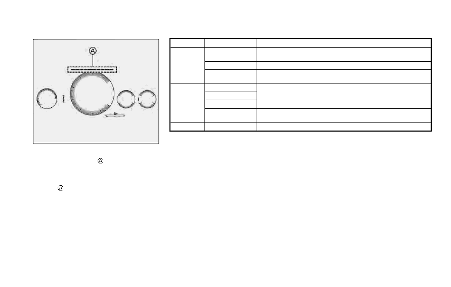
UPSHIFT INDICATOR
The upshift indicator
is displayed in the
sports mode display and shows the driver
the timing to shift into a higher gear by
illuminating. The use of the upshift in-
dicator
will help you to upshift at a
constant engine speed from any gear.
The upshift indicator can be customized.
The options are shown in the following
table. (See “Vehicle information display”
(P.2-10).)
Mode
Indication color
Conditions
Customi-
zation
Green
Illuminates about 1,800 to 2,400 rpm before the set engine
speed.
Yellow
Illuminates about 600 to 1,200 rpm before the set engine speed.
Red (illuminate)
Illuminates when the engine speed reaches the set engine
speed.
Auto
Green
The engine speed that illuminates is set automatically accord-
ing to each gear position.
Yellow
Red (illuminate)
Red (flash)
Flashes when the engine speed reaches near the maximum
engine speed.
OFF
No color
Indicator is off at all times.
It is notified that the shift-up timing is
imminent when two segments of yellow
indicators illuminate. Please shift into the
higher gear at the latest when the upshift
indicator illuminates in red. If the upshift
indicator flashes in red, the fuel supply will
be restricted to protect the engine.
Starting and driving
5-25