Nissan Frontier (2022 year). Manual in english - page 28


  Index      Manuals     Nissan Frontier (2022 year). Manual in english


Search            copyright infringement  


Content      ..     26      27      28      29     ..


Nissan Frontier (2022 year). Manual in english - page 28


NISSAN INTELLIGENT KEY®

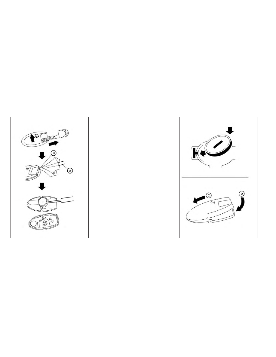
Replace the battery in the Intelligent Key as
follows:

1. Remove the mechanical key from the

Intelligent Key.

2. Insert a small flathead screwdriver

O

A

into the slit

O

B

of the corner and twist it

to separate the upper part from the
lower part. Place a cloth over the screw-
driver to protect the casing.

LDI2001

LDI2637

8-24

Do-it-yourself

-------------------------------------------------------------------------------------------------------------------------------------------------------------

3. Replace the battery with a new one.

Recommended

battery:

CR2032

or

equivalent.

• Do not touch the internal circuit and

electric terminals as doing so could
cause a malfunction.

• Hold the battery by the edges. Holding

the battery across the contact points
will seriously deplete the storage
capacity.

• Make sure that the + side faces the

bottom of the lower part.

4. Close the lid securely as illustrated with

O

C

and

O

D

.

5. Operate the buttons to check the

operation.

If you need assistance with replacement, it
is recommended that you visit a NISSAN
dealer for this service.

FCC Notice:

For USA:
This device complies with Part 15 of the
FCC Rules. Operation is subject to the fol-
lowing two conditions: (1) This device
may not cause harmful interference, and
(2) this device must accept any interfer-
ence received, including interference
that may cause undesired operation.

Note:

Changes or modifications not expressly
approved by the party responsible for
compliance could void the user’s author-
ity to operate the equipment.

For Canada:
This

device

contains

licence-exempt

transmitter(s)/receiver(s) that comply
with Innovation, Science and Economic
Development Canada’s licence-exempt
RSS(s). Operation is subject to the fol-
lowing two conditions: (1) This device
may not cause interference. (2) This de-
vice must accept any interference, in-
cluding interference that may cause un-
desired operation of the device.

HEADLIGHTS

For additional information on headlight
bulb replacement, refer to the instructions
outlined in this section.

Replacing the halogen headlight
bulb (if so equipped)

The headlight is a semi-sealed beam type
which uses a replaceable headlight (halo-
gen) bulb. Because the headlight assembly
must be removed from the vehicle for bulb
replacement, it is recommended that you
visit a NISSAN dealer for this service.

CAUTION

High pressure halogen gas is sealed
inside the halogen bulb. The bulb
may break if the glass envelope is
scratched or the bulb is dropped.

When handling the bulb, do not touch
the glass envelope.

DO NOT TOUCH THE BULB WITH BARE
HANDS.

Use the same number and wattage
as shown in the chart.

LIGHTS

Do-it-yourself

8-25

-------------------------------------------------------------------------------------------------------------------------------------------------------------

Do not leave the bulb out of the head-
light reflector for a long period of
time as dust, moisture and smoke
may enter the headlight body and af-
fect

the

performance

of

the

headlight.

Aiming is not necessary after replac-
ing the bulb. When aiming adjust-
ment is necessary, it is recom-
mended that you visit a NISSAN
dealer for this service.

Fog may temporarily form inside the lens
of the exterior lights in the rain or in a car
wash. A temperature difference between
the inside and the outside of the lens
causes the fog. This is not a malfunction. If
large drops of water collect inside the lens,
it is recommended that you visit a NISSAN
dealer for servicing.

Replacing the LED headlight bulb
(if so equipped)

If LED headlight bulb replacement is re-
quired, it is recommended that you visit a
NISSAN dealer for this service.

FOG LIGHTS (if so equipped)

For additional information on fog light bulb
replacement, refer to the instructions out-
lined in this section.

Replacing the fog light bulb (if so
equipped)

If fog light bulb replacement is required, it is
recommended that you visit a NISSAN
dealer for this service.

CAUTION

High pressure halogen gas is sealed
inside the halogen bulb. The bulb
may break if the glass envelope is
scratched or the bulb is dropped.

When handling the bulb, do not touch
the glass envelope.

Use the same number and wattage
as originally installed as shown in the
chart.

Do not leave the bulb out of the fog
light for a long period of time as dust,
moisture and smoke may enter the
fog light body and affect the perfor-
mance of the fog light.

Replacing the LED fog light bulb (if
so equipped)

If LED fog light bulb replacement is re-
quired, it is recommended that you visit a
NISSAN dealer for this service.

8-26

Do-it-yourself

-------------------------------------------------------------------------------------------------------------------------------------------------------------

EXTERIOR AND INTERIOR LIGHTS

Item

Wattage (W)

Bulb No.*

Headlight assembly (Type A) (if so equipped)*

Low/High

55/65

HB5

Turn/Park

28/8

7444NA

Side marker

Headlight assembly (Type B) (if so equipped)*

Low

High

Turn

Daytime Running Light (DRL)/Park

Side marker

Fog light (if so equipped)*

Fog light assembly (if so equipped)*

Fog

21

W21W

Daytime Running Light (DRL)

35

H8

Map light (Type A) (if so equipped)

8

Map light (Type B) (if so equipped)*

Vanity mirror light (if so equipped)*

1.4

Room light (Type A) (if so equipped)

8

Room light (Type B) (if so equipped)*

Glove box light (if so equipped)*

1

High-mounted stop light/cargo light*

12.8

912

Bed light (if so equipped)*

Rear combination light*

Tail

Stop/turn

Back-up

License plate light*

* It is recommended that you visit an NISSAN dealer for replacement.

Always check with the Parts Department at
a NISSAN dealer for the latest parts
information.

Do-it-yourself

8-27

-------------------------------------------------------------------------------------------------------------------------------------------------------------

1.

Room light

2.

Map light

3.

Headlight assembly

4.

Fog light/Fog light assembly (if so
equipped)

5.

Bed light (if so equipped)

6.

High-mount stop light/cargo light

7.

Rear combination light

8.

License plate light

LDI3631

8-28

Do-it-yourself

-------------------------------------------------------------------------------------------------------------------------------------------------------------

Replacement procedures

All other lights are either type A, B, C or D.
When replacing a bulb, first remove the lens
and/or cover using a cloth and suitable tool.

: Indicates bulb removal
: Indicates bulb installation

Use a cloth

O

1

to protect the housing.

Use a cloth

O

1

to protect the housing.

WDI0306

LDI0478

Map light (Type A) (if so equipped)

WDI0206

Room light (Type A) (if so equipped)

Do-it-yourself

8-29

-------------------------------------------------------------------------------------------------------------------------------------------------------------

If you have a flat tire, see “Flat tire”
(P. 6-3).

TIRE PRESSURE

Tire Pressure Monitoring System
(TPMS)

WARNING

Radio waves could adversely af-
fect electric medical equipment.
Those who use a pacemaker
should contact the electric medi-
cal equipment manufacturer for
the possible influences before
use.

This vehicle is equipped with TPMS. It
monitors tire pressure of all tires ex-
cept the spare. When the low tire
pressure warning light is lit and the
“Tire Pressure Low - Add Air” warning
message is displayed in the vehicle
information display, one or more of
your

tires

is

significantly

under-inflated.

TPMS will activate only when the ve-
hicle is driven at speeds above 16
mph (25 km/h). Also, this system
may not detect a sudden drop in tire
pressure (for example, a flat tire while
driving).

For additional information, see “Low
tire pressure warning light” (P. 2-15),
“Tire Pressure Monitoring System
(TPMS)” (P. 5-5) and “Flat tire” in the
(P. 6-3).

Tire inflation pressure

Check the tire pressures (including
the spare) often and always prior to
long distance trips. The recom-
mended tire pressure specifications
are shown on the F.M.V.S.S./C.M.V.S.S.
certification label or the Tire and
Loading Information label under the
“Cold Tire Pressure” heading. The Tire
and Loading Information label is af-
fixed to the driver side center pillar.

Tire pressures should be checked
regularly because:

• Most tires naturally lose air over

time.

• Tires can lose air suddenly when

driven over potholes or other ob-
jects or if the vehicle strikes a curb
while parking.

The

tire

pressures

should

be

checked when the tires are cold. The
tires are considered COLD after the
vehicle has been parked for 3 or
more hours, or driven less than 1 mile
(1.6 km) at moderate speeds.

Incorrect tire pressure, including
under inflation, may adversely af-
fect tire life and vehicle handling.

WHEELS AND TIRES

8-30

Do-it-yourself

-------------------------------------------------------------------------------------------------------------------------------------------------------------

WARNING

Improperly inflated tires can
fail suddenly and cause an
accident.

The Gross Vehicle Weight Rat-
ing (GVWR) is located on the
F.M.V.S.S./C.M.V.S.S.

certifica-

tion label. The vehicle weight
capacity is indicated on the Tire
and Loading Information label.
Do not load your vehicle be-
yond this capacity. Overload-
ing your vehicle may result in
reduced tire life, unsafe operat-
ing conditions due to prema-
ture tire failure, or unfavorable
handling characteristics and
could also lead to a serious ac-
cident. Loading beyond the
specified capacity may also re-
sult in failure of other vehicle
components.

Before taking a long trip, or
whenever

you

heavily

load

your vehicle, use a tire pressure
gauge to ensure that the tire
pressures are at the specified
level.

For additional information re-
garding tires, refer to “Impor-
tant Tire Safety Information”
(US) or “Tire Safety Informa-
tion” (Canada) in the Warranty
Information Booklet.

Do-it-yourself

8-31

-------------------------------------------------------------------------------------------------------------------------------------------------------------

Tire and Loading Information
label

1

Seating capacity: The maximum
number of occupants that can
be seated in the vehicle.

2

Vehicle load limit: See “Vehicle
loading information” (P. 10-16).

3

Original tire size: The size of the
tires originally installed on the ve-
hicle at the factory.

4

Cold tire pressure: Inflate the tires
to this pressure when the tires
are cold. Tires are considered
COLD after the vehicle has been
parked for 3 or more hours, or
driven less than 1 mile (1.6 km) at
moderate speeds. The recom-
mended cold tire inflation is set
by the manufacturer to provide
the best balance of tire wear, ve-

hicle handling, driveability, tire
noise, etc., up to the vehicle's
GVWR.

5

Tire

size:

See

“Tire

labeling”

(P. 8-34).

6

Spare tire size.

LDI2007

8-32

Do-it-yourself

-------------------------------------------------------------------------------------------------------------------------------------------------------------

Checking tire pressure

1. Remove the valve stem cap from

the tire.

2. Press

the

pressure

gauge

squarely onto the valve stem. Do
not press too hard or force the
valve stem sideways, or air will es-
cape. If the hissing sound of air
escaping from the tire is heard
while checking the pressure, re-
position the gauge to eliminate
this leakage.

3. Remove the gauge.

4. Read the tire pressure on the

gauge stem and compare to the
specification

shown

on

the

F.M.V.S.S./C.M.V.S.S. label or the
Tire

and

Loading

Information

label.

5. Add air to the tire as needed. If too

much air is added, press the core
of the valve stem briefly with the
tip of the gauge stem to release
pressure. Recheck the pressure
and add or release air as needed.

6. Install the valve stem cap.

7. Check the pressure of all other

tires, including the spare.

Size

Cold Tire Infla-
tion Pressure

Front and Rear
Original Tire:
P265/70R16
265/65R17
265/70R17

35 psi, 240 kPa

Front and Rear
Original Tire Size:
P265/70R16
265/65R17
265/70R17

Spare Tire
Size:
Full Size
P265/70R16
Full Size

LDI0393

Do-it-yourself

8-33

-------------------------------------------------------------------------------------------------------------------------------------------------------------

TIRE LABELING

Federal law requires tire manufac-
turers to place standardized infor-
mation on the sidewall of all tires.
This information identifies and de-
scribes the fundamental character-
istics of the tire and also provides the
Tire Identification Number (TIN) for
safety standard certification. The TIN
can be used to identify the tire in
case of a recall.

O

1

Tire size (example: P215/65R15

95H)

1. P: The “P” indicates the tire is de-

signed for passenger vehicles (not
all tires have this information).

2. Three-digit number (215): This

number gives the width in milli-
meters of the tire from sidewall
edge to sidewall edge.

3. Two-digit number (65): This num-

ber, known as the aspect ratio,
gives the tire's ratio of height to
width.

4. R: The “R” stands for radial.

5. Two-digit number (15): This num-

ber is the wheel or rim diameter in
inches.

WDI0394

Example

WDI0395

Example

8-34

Do-it-yourself

-------------------------------------------------------------------------------------------------------------------------------------------------------------

6. Two- or three-digit number (95):

This number is the tire's load in-
dex. It is a measurement of how
much

weight

each

tire

can

support.

7. H: Tire speed rating. You should

not drive the vehicle faster than
the tire speed rating.

O

2

TIN (Tire Identification Number)

for a new tire (example: DOT XX XX
XXX XXXX)

1. DOT: Abbreviation for the “Depart-

ment

Of

Transportation”.

The

symbol can be placed above, be-
low or to the left or right of the Tire
Identification Number.

2. Two-digit code: Manufacturer's

identification mark.

3. Two-digit code: Tire size.

4. Three-digit code: Tire type code

(Optional).

5. Four

numbers

represent

the

week and year the tire was built.
For example, the numbers 3103
means the 31st week of 2003. If
these numbers are missing then
look on the other sidewall of the
tire.

LDI2786

Example (Type A) (if so equipped)

Do-it-yourself

8-35

-------------------------------------------------------------------------------------------------------------------------------------------------------------

O

2

TIN (Tire Identification Number)

for a new tire (example: DOT XXX
XXXXXX XXXX)

1. DOT: Abbreviation for the “Depart-

ment

Of

Transportation”.

The

symbol can be placed above, be-
low or to the left of the Tire Identi-
fication Number.

2. Three-digit code: Manufacturer's

identification mark.

3. Six-digit code: Descriptive code

used to identify significant char-
acteristics of the tire.

4. Four

numbers

represent

the

week and year the tire was built.
For example, the numbers 3103
means the 31st week of 2003.

O

3

Tire ply composition and material

The number of layers or plies of
rubber-coated fabric in the tire. Tire
manufacturers also must indicate
the materials in the tire, which in-
clude steel, nylon, polyester and
others.

O

4

Maximum permissible inflation

pressure

This number is the greatest amount
of air pressure that should be put in
the tire. Do not exceed the maximum
permissible inflation pressure.

O

5

Maximum load rating

This number indicates the maxi-
mum load in kilograms and pounds
that can be carried by the tire. When
replacing the tires on the vehicle, al-
ways use a tire that has the same
load rating as the factory installed
tire.

LDI3639

Example (Type B) (if so equipped)

8-36

Do-it-yourself

-------------------------------------------------------------------------------------------------------------------------------------------------------------

O

6

Term of “tubeless” or “tube type”

Indicates whether the tire requires
an inner tube (“tube type”) or not
(“tubeless”).

O

7

The word “radial”

The word “radial” is shown if the tire
has radial structure.

O

8

Manufacturer or brand name

Manufacturer or brand name is
shown.

Other Tire-related Terminology

In addition to the many terms that
are defined throughout this section,
Intended Outboard Sidewall is (1) the
sidewall that contains a whitewall,
bears

white

lettering

or

bears

manufacturer, brand, and/or model
name molding that is higher or
deeper than the same molding on
the other sidewall of the tire, or (2)
the outward facing sidewall of an
asymmetrical tire that has a particu-

lar side that must always face out-
ward when mounted on a vehicle.

TYPES OF TIRES

WARNING

When changing or replacing tires, be
sure all four tires are of the same type
(i.e., Summer, All Season or Snow)
and construction. A NISSAN dealer
may be able to help you with infor-
mation about tire type, size, speed
rating and availability.

Replacement tires may have a lower
speed

rating

than

the

factory

equipped tires, and may not match
the

potential

maximum

vehicle

speed. Never exceed the maximum
speed rating of the tire.

Replacing tires with those not origi-
nally specified by NISSAN could af-
fect the proper operation of the low
tire pressure warning system.

Always use tires of the same type,
size, brand, construction and tread
pattern on all four wheels. Failure to
do so may result in a circumference
difference between tires on the front
and rear axles which can cause the
Vehicle Dynamic Control (VDC) sys-
tem to malfunction resulting in per-
sonal injury or death, excessive tire
wear and may damage the transmis-
sion and differential gears.

For additional information regarding
tires, refer to “Important Tire Safety
Information” (US) or “Tire Safety In-
formation” (Canada) in the Warranty
Information Booklet.

All season tires

NISSAN specifies All Season tires on some
models to provide good performance all
year, including snowy and icy road condi-
tions. All Season tires are identified by ALL
SEASON and/or M&S on the tire sidewall.
Snow tires have better snow traction than
All Season tires and may be more appropri-
ate in some areas.

Do-it-yourself

8-37

-------------------------------------------------------------------------------------------------------------------------------------------------------------

Summer tires

NISSAN specifies summer tires on some
models to provide superior performance
on dry roads. Summer tire performance is
substantially reduced in snow and ice.
Summer tires do not have the tire traction
rating “M&S” on the tire sidewall.

If you plan to operate your vehicle in snowy
or icy conditions, NISSAN recommends the
use of SNOW tires or ALL SEASON tires on all
four wheels.

Snow tires

If snow tires are needed, it is necessary to
select tires equivalent in size and load rat-
ing to the original equipment tires. If you do
not, it can adversely affect the safety and
handling of your vehicle.

Generally, snow tires have lower speed rat-
ings than factory equipped tires and may
not match the potential maximum vehicle
speed. Never exceed the maximum speed
rating of the tire.

If you install snow tires, they must be the
same size, brand, construction and tread
pattern on all four wheels.

For additional traction on icy roads, stud-
ded tires may be used. However, some U.S.

states and Canadian provinces prohibit
their use. Check local, state and provincial
laws before installing studded tires. Skid
and traction capabilities of studded snow
tires on wet or dry surfaces may be poorer
than that of non-studded snow tires.

TIRE CHAINS

Use of tire chains may be prohibited ac-
cording to location. Check the local laws
before installing tire chains. When installing
tire chains, make sure they are the proper
size for the tires on your vehicle and are
installed according to the chain manufac-
turer's suggestions.

Use only SAE class “S”

chains.

Class “S” chains are used on ve-

hicles with restricted tire to vehicle clear-
ance. Vehicles that can use Class “S” chains
are designed to meet the minimum clear-
ances between the tire and the closest ve-
hicle suspension or body component re-
quired to accommodate the use of a
winter traction device (tire chains or
cables). The minimum clearances are de-
termined using the factory equipped tire
size. Other types may damage your vehicle.
Use chain tensioners when recommended
by the tire chain manufacturer to ensure a
tight fit. Loose end links of the tire chain
must be secured or removed to prevent
the possibility of whipping action damage

to the fenders or underbody. If possible,
avoid fully loading your vehicle when using
tire chains. In addition, drive at a reduced
speed. Otherwise, your vehicle may be
damaged and/or vehicle handling and
performance may be adversely affected.

Tire chains must be installed only on the
rear wheels and not on the front wheels.

Do not use tire chains on dry roads. Driving
with chains in such conditions can cause
damage to the various mechanisms of the
vehicle due to some overstress.

Use only the 2WD range when driving on
clear paved roads.

8-38

Do-it-yourself

-------------------------------------------------------------------------------------------------------------------------------------------------------------

CHANGING WHEELS AND TIRES

Tire rotation

NISSAN recommends rotating the
tires every 7,500 miles (12,000 km).

For additional information on tire re-
placing procedures, see “Flat tire”
(P. 6-3).

As soon as possible, tighten the
wheel nuts to the specified torque
with a torque wrench.

Wheel nut tightening torque:

98 ft-lb (133 ft-lb)

The wheel nuts must be kept tight-
ened to specifications at all times.
It is recommended that wheel nuts
be tightened to specification at
each tire rotation interval.

WARNING

After rotating the tires, check
and adjust the tire pressure.

Retighten the wheel nuts when
the vehicle has been driven for
600 miles (1,000 km) (also in
cases of a flat tire, etc.).

Do not include the spare tire in
the tire rotation.

For additional information re-
garding tires, refer to “Impor-
tant Tire Safety Information”
(US) or “Tire Safety Informa-
tion” (Canada) in the Warranty
Information Booklet.

Tire wear and damage

1. Wear indicator

2. Location mark

WDI0258

WDI0259

Do-it-yourself

8-39

-------------------------------------------------------------------------------------------------------------------------------------------------------------


Content      ..     26      27      28      29     ..