Nissan Frontier (2022 year). Manual in english - page 10


  Index      Manuals     Nissan Frontier (2022 year). Manual in english


Search            copyright infringement  


Content      ..     8      9      10      11     ..


Nissan Frontier (2022 year). Manual in english - page 10


WARNING

When the LED DRL system is active, tail
lights on your vehicle are not on. It is
necessary at dusk to turn on your
headlights. Failure to do so could cause
an

accident

injuring

yourself

and

others.

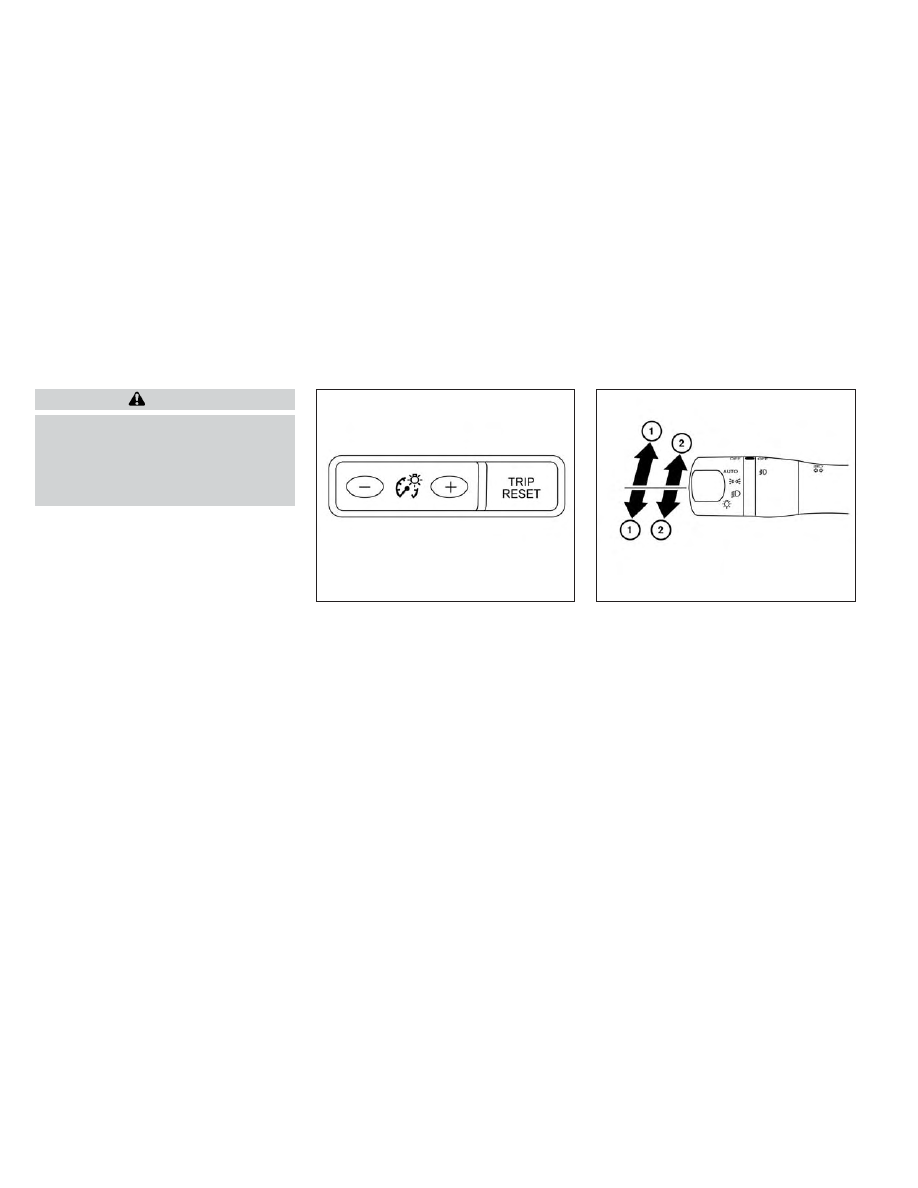
INSTRUMENT BRIGHTNESS
CONTROL

Press the “+” button to increase the bright-
ness of instrument panel lights.

Press the “-” button to decrease the bright-
ness of instrument panel lights.

TURN SIGNAL SWITCH

Turn signal

1

Move the lever up or down to signal the
turning direction. When the turn is com-
pleted,

the

turn

signal

cancels

automatically.

Lane change signal

2

Move the lever up or down until the turn
signal begins to flash, but the lever
does not latch, to signal a lane change.
Hold the lever until the lane change is
complete.

LIC3176

LIC3252

2-44

Instruments and controls

-------------------------------------------------------------------------------------------------------------------------------------------------------------

FOG LIGHT SWITCH (if so
equipped)

To turn the fog lights on, turn the headlight
switch to the

position, then turn the

fog light switch to the

position.

To turn the fog lights on with the headlight
switch in the AUTO position (if so equipped),
the headlights must be on, then turn the
fog light switch to the

position.

To turn the fog lights off, turn the fog light
switch to the OFF position.

The headlights must be on and the low
beams selected for the fog lights to oper-
ate. The fog lights automatically turn off
when the high beam headlights are
selected.

To sound the horn, push the area between
the horn icons on the steering wheel.

WARNING

Do not disassemble the horn. Doing so
could affect proper operation of the
supplemental front air bag system.
Tampering

with

the

supplemental

front air bag system may result in seri-
ous personal injury.

LIC3256

LIC4829

HORN

Instruments and controls

2-45

-------------------------------------------------------------------------------------------------------------------------------------------------------------

To turn on the cargo lamp, push the switch
down to the ON position.

CAUTION

Be sure to turn the light switch to the
OFF position when you leave the ve-
hicle for extended periods of time, oth-
erwise the battery will go dead.

The front seats are warmed by built-in
heaters.

1. Place the ignition switch in the ON

position.

2. Push the LO or HI position of the switch,

as desired, depending on the tempera-
ture. The indicator light in the switch will
illuminate.

The heater is controlled by a thermostat,
automatically turning the heater on and
off. The indicator light will remain on as
long as the switch is on.

3. When the seat is warmed or before you

leave the vehicle, be sure to turn the
switch off.

WARNING

Do not use or allow occupants to use
the seat heater if you or the occupants
cannot monitor elevated seat tem-
peratures or have an inability to feel
pain in body parts that contact the
seat. Use of the seat heater by such
people could result in serious injury.

CAUTION

Do not use the seat heater for ex-
tended periods or when no one is us-
ing the seat.

Do not put anything on the seat
which insulates heat, such as a blan-
ket, cushion, seat cover, etc. Other-
wise,

the

seat

may

become

overheated.

Do not place anything hard or heavy
on the seat or pierce it with a pin or
similar object. This may result in
damage to the heater.

LIC0616

LIC3762

CARGO LAMP SWITCH

HEATED SEAT SWITCHES (if so
equipped)

2-46

Instruments and controls

-------------------------------------------------------------------------------------------------------------------------------------------------------------

Any liquid spilled on the heated seat
should be removed immediately with
a dry cloth.

When cleaning the seat, never use
gasoline, benzine, thinner, or any
similar materials.

If any malfunctions are found or the
heated seat does not operate, turn
the switch off and have the system
checked. It is recommended that you
visit a NISSAN dealer for this service.

The battery could run down if the
seat heater is operated while the en-
gine is not running.

The heated steering wheel system is de-
signed to operate only when the surface
temperature of the steering wheel is below
68°F (20°C).

Push the heated steering wheel switch to
warm the steering wheel after the engine
starts. The indicator light will come on.

If the surface temperature of the steering
wheel is below 68°F (20°C), the system will
heat the steering wheel and cycle off and
on to maintain a temperature above 68°F
(20°C). The indicator light will remain on as
long as the system is on.

Push the switch again to turn the heated
steering wheel system off manually. The
indicator light will go off. The switch will turn
off automatically 30 minutes after activa-
tion, once this happens the switch will need
to be pressed again to restart the cycle.

NOTE:

If the surface temperature of the steer-
ing wheel is above 68°F (20°C) when the
switch is turned on, the system will not
heat the steering wheel. This is not a
malfunction.

LIC4582

HEATED STEERING WHEEL SWITCH (if
so equipped)

Instruments and controls

2-47

-------------------------------------------------------------------------------------------------------------------------------------------------------------

The warning systems switch is used to turn
on and off the following systems that are
activated using the Settings menu in the
vehicle information display:
• Blind Spot Warning (BSW) (if so equipped)
• Lane Departure Warning (LDW) (if so

equipped)

When the warning systems switch is
turned off, the indicator

O

1

on the switch is

off. The indicator will also be off if all of the
warning systems are deactivated using
the settings menu.

The BSW system will turn on the side indi-
cator lights, located by the outside mirrors,
if the radar sensors detect a vehicle in the
detection zone. If the turn signal is acti-
vated in the direction of the detected ve-
hicle, a chime sounds twice and the side
indicator light will flash.

The LDW system will sound a warning; the
steering wheel will vibrate; and the LDW
indicator (orange) will blink to alert the
driver of the vehicle is traveling close to
either the left or the right of a traveling lane
with detectable lane markers.

For additional information, see “Blind Spot
Warning (BSW)” (P. 5-32) and “Lane Depar-
ture Warning (LDW)” (P. 5-27).

The vehicle should be driven with the VDC
system on for most driving conditions.

If the vehicle is stuck in mud or snow, the
VDC system reduces the engine output to
reduce wheel spin. The engine speed will
be reduced even if the accelerator is de-
pressed to the floor. If maximum engine
power is needed to free a stuck vehicle,
turn the VDC system off.

To turn off the VDC system, push the VDC
OFF switch. The

indicator will come

on.

LIC2225

LIC3344

WARNING SYSTEMS SWITCH (if so
equipped)

VEHICLE DYNAMIC CONTROL (VDC)
OFF SWITCH

2-48

Instruments and controls

-------------------------------------------------------------------------------------------------------------------------------------------------------------

Push the VDC OFF switch again or restart
the engine to turn on the system. For addi-
tional information, see “Vehicle Dynamic
Control (VDC) system” (P. 5-121).

WARNING

Never rely solely on the hill descent
control system to control vehicle
speed when driving on steep down-
hill grades. Always drive carefully
when using the hill descent control
system and decelerate the vehicle
speed by depressing the brake pedal
if necessary. Be especially careful
when driving on frozen, muddy or ex-
tremely steep downhill roads. Failure
to control vehicle speed may result in
a loss of control of the vehicle and
possible serious injury or death.

The hill descent control may not con-
trol the vehicle speed on a hill under
all load or road conditions. Always be
prepared to depress the brake pedal
to control vehicle speed. Failure to do
so may result in a collision or serious
personal injury.

CAUTION

When the hill descent control system
operates continuously for a long time,
the temperature of the brake pads may
increase and the hill descent control
system may be temporarily disabled
(the indicator light will blink). If the indi-
cator light does not come on continu-
ously after blinking, stop using the
system.

LIC0743

HILL DESCENT CONTROL SWITCH (if
so equipped)

Instruments and controls

2-49

-------------------------------------------------------------------------------------------------------------------------------------------------------------

The hill descent control system is designed
to reduce driver workload when going
down steep hills. The hill descent control
system helps to control vehicle speed so
the driver can concentrate on steering the
vehicle.

To activate the hill descent control system:
• The shift lever must be in forward or re-

verse gear,

• The 4WD switch must be in the 4L posi-

tion and the vehicle speed must be under
15 mph (25 km/h) or

• The 4WD switch must be in the 4H posi-

tion and the vehicle speed must be under
21 mph (35 km/h), and

• The hill descent control system switch

must be ON.

The hill descent control system ON indica-
tor light will come on when the system is
activated. Also, the stop/tail lights illumi-
nate while the hill descent control system
applies the brakes to control vehicle speed.

If the accelerator or brake pedal is de-
pressed while the hill descent control sys-
tem is on, the system will stop operating
temporarily. As soon as the accelerator or
brake pedal is released, the hill descent
control system begins to function again if
the hill descent control operating condi-
tions are fulfilled.

The hill descent control system ON indica-
tor light blinks if the switch is on and all
conditions for system activation are not
met or if the system becomes disengaged
for any reason.

To turn off the hill descent control system,
push the switch to the OFF position.

For additional information, see “Hill descent
control system ON indicator light” (P. 2-15)
and “Hill descent control system” (P. 5-123).

The E-Lock system can help provide added
traction if the vehicle is stuck or becoming
stuck.

To activate the E-Lock system:
• The 4WD switch must be in the 4LO posi-

tion (4-Wheel Drive vehicles),

• The vehicle must be stopped or moving

at 4 mph (7 km/h) or less, and

• The E-Lock system switch must be

turned on.

LIC0729

ELECTRONIC LOCKING REAR
DIFFERENTIAL (E-Lock) SYSTEM
SWITCH (if so equipped)

2-50

Instruments and controls

-------------------------------------------------------------------------------------------------------------------------------------------------------------

When the E-Lock switch is turned on, the
indicator light will flash until the system
engages. However, if all operation condi-
tions listed above are not met or the sys-
tem becomes disengaged, the indicator
light will continue to flash.

The Anti-lock Braking System (ABS) is dis-
abled and the ABS light illuminates when
the E-Lock system is on. Also, the Vehicle
Dynamic Control (VDC) system is disabled
and the VDC light illuminates when the
E-Lock system is on.

For additional information, see “Electronic
locking rear differential (E-Lock) system”
(P. 5-116) for further explanation and system
limitations.

WARNING

Never leave the E-Lock system on
when driving on paved or hard-
surfaced roads. Turning the vehicle
may result in the rear wheels slipping
and result in an accident and per-
sonal injury. After using the E-Lock
system to free the vehicle, turn the
system off.

Use the E-Lock system only when
freeing a stuck vehicle. Try the 4LO
position before using the E-Lock sys-
tem. Never use the E-Lock system on
a slippery road surface such as snow
or ice surface. Using the E-Lock sys-
tem when driving in these road con-
ditions

may

cause

unexpected

movement of the vehicle during en-
gine braking, accelerating or turning,
which may result in an accident and
serious personal injury.

CAUTION

After using the E-Lock system, turn
the switch off to prevent possible
damage to driveline components
from extended use.

Do not drive over 12 mph (20 km/h)
when the system is engaged. Doing
so could result in possible damage to
the driveline.

Do not turn on the E-Lock system
while the tires are spinning. Doing so
could

damage

drivetrain

components.

To use the outlets for devices that require
up to 120v power, the vehicle must be run-
ning and the power inverter switch must
be on.

When the vehicle is in the P (Park) position,
the 400W and the 150W will automatically
illuminate. When the vehicle is out of the P
(Park) position, only 150W will illuminate.

For additional information, see “120v out-
lets” (P. 2-56) regarding using devices that
require the power inverter switch to be
activated.

LIC4847

POWER INVERTER SWITCH (if so
equipped)

Instruments and controls

2-51

-------------------------------------------------------------------------------------------------------------------------------------------------------------

CAUTION

Use power outlets with the engine
running to avoid discharging the ve-
hicle battery.

Do not attempt to use this while
driving.

Do not use double adapters or more
than one electrical accessory, doing
so could significantly drain the bat-
tery of your vehicle.

The Parking Aids system switch on the in-
strument panel allows the driver to turn
the following systems (if so equipped) on
and off. To turn the systems on and off, the
ignition switch must be in the ON position.
• Rear Sonar System (RSS) (if so equipped)
• Moving Object Detection (MOD) (if so

equipped)

• Rear Automatic Braking (RAB) (if so

equipped)

• Rear Cross Traffic Alert (RCTA) (if so

equipped)

The indicator light on the switch will illumi-
nate when the systems are turned on.

If the indicator light flashes when the RSS,
MOD, RAB, or RCTA systems are not turned
off, it may indicate a malfunction in one or
more of these systems (if so equipped).

The RSS, MOD, RAB, or RCTA systems will be
turned on automatically under the follow-
ing conditions:
• When the ignition switch is switched from

the OFF position to the ON position.

• When the shift lever is shifted into the R

(Reverse) position.

The automatic turning on function can be
turned on and off for these systems in the
vehicle information display. For additional
information, see “Settings” (P. 2-21).

For additional information, see “Rear Sonar
System (RSS)” (P. 5-124), ”Rear Automatic
Braking (RAB)” (P. 5-76), “Rear Cross Traffic
Alert (RCTA)” (P. 5-43), or “Moving Object De-
tection (MOD)” (P. 4-22).

LIC3596

PARKING AIDS SYSTEM SWITCH (if so
equipped)

2-52

Instruments and controls

-------------------------------------------------------------------------------------------------------------------------------------------------------------

Tow mode should be used when pulling a
heavy trailer or hauling a heavy load. Driv-
ing the vehicle in the tow mode with no
trailer/load or light trailer/light load will not
cause

any

damage.

However,

fuel

economy

may

be

reduced,

and

the

transmission/engine driving characteris-
tics may feel unusual.

Push the tow mode switch to activate tow
mode. The TOW indicator light illuminates
when tow mode is selected. Push the tow
mode switch again to turn tow mode off.

Tow mode is automatically canceled when
the ignition switch is placed in the OFF
position.

For additional information, see “Towing a
trailer” (P. 10-27).

The Emergency call (SOS) system button is
used

in

combination

with

a

NissanConnect® Services subscription to
call for assistance in case of an emergency.

Pushing the button will (with a paid sub-
scription) reach a Response Specialist that
will provide assistance based on the situa-
tion described by the vehicle’s occupant.
For additional information, or to enroll your
vehicle,

refer

to

www.NissanUSA.com/

connect or call 855–426–6628.

LIC4845

LIC3376

TOW MODE SWITCH (if so equipped)

EMERGENCY CALL (SOS) BUTTON (if
so equipped)

Instruments and controls

2-53

-------------------------------------------------------------------------------------------------------------------------------------------------------------

The Rear Door Alert system functions un-
der certain conditions to indicate there
may be an object or passenger in the rear
seat(s). Check the seat(s) before exiting the
vehicle.

The Rear Door Alert system is initially dis-
abled. The driver can enable the system
using the vehicle information display. For
additional information, see “Vehicle infor-
mation display warnings and indicators”
(P. 2-28).

When the system is enabled:
• The system is activated when a rear door

is opened and closed within 10 minutes of
the vehicle being driven. When the driver’
door is closed and the system is acti-
vated, a visual message appears in the
vehicle information display. For additional
information, see “Rear Door Alert is acti-
vated” (P. 2-30).

• If a rear door is opened and closed but

the vehicle is not driven within approxi-
mately 10 minutes, the system will not be
activated. A rear door must be opened
and closed and the car driven within 10
minutes for the system to activate.

When the Rear Door Alert system is acti-
vated and a driver exits the vehicle after
arriving at a destination:
• When the driver puts the vehicle in the P

(Park) position, a message appears in the
vehicle information display for a driver to
“Dismiss Message” or “Disable Alert” if
desired.

• With the system enabled, when the driver

exits the vehicle, an audible alert (horn
sound) will occur unless a rear door is
opened and closed within a short time to
deactivate the alert.

• If the doors are locked before the alert is

deactivated by opening a rear door, the
horn will sound.

• If the audible horn alert occurs, a mes-

sage will also appear in the vehicle infor-
mation display that states, “Check Rear
Seat for All Articles”.

WARNING

• If the driver selects “Disable Alert”, no
audible alert will be provided regard-
less of rear door open/close status.

• There may be times when there is an
object or passenger in the rear seat(s)
but the audible alert does not sound.
For example, this may occur if rear seat
passengers enter or exit the vehicle
during a trip.

• The system does not directly detect
objects or passengers in the rear
seat(s). Instead, it can detect when a
rear door is opened and closed, indicat-
ing that there may be something in the
rear seat(s).

NOTE:

There may be times when the horn
sounds but there are no objects or pas-
sengers in the rear seat(s).

For additional information, see “Rear Door
Alert is activated” (P. 2-30).

REAR DOOR ALERT

2-54

Instruments and controls

-------------------------------------------------------------------------------------------------------------------------------------------------------------

12V OUTLETS

The power outlets are for powering electri-
cal

accessories

such

as

cellular

telephones.

The power outlets located on the instru-
ment panel and inside the center armrest
are powered only when the ignition switch
is placed in the ACC or ON position.

Open the cap to use a power outlet.

CAUTION

The outlet and plug may be hot dur-
ing or immediately after use.

Only certain power outlets are de-
signed for use with a cigarette lighter
unit. Do not use any other power out-
let for an accessory lighter. It is rec-
ommended that you visit a NISSAN
dealer for additional information.

Do not use with accessories that ex-
ceed a 12 volt, 120W (10A) power draw.

Do not use double adapters or more
than one electrical accessory.

Use power outlets with the engine
running to avoid discharging the ve-
hicle battery.

Avoid using power outlets when the
air conditioner, headlights, or rear
window defroster (if so equipped) is
on.

Before inserting or disconnecting a
plug, be sure the electrical accessory
being used is turned OFF.

Push the plug in as far as it will go. If
good contact is not made, the plug
may overheat or the internal tem-
perature fuse may open.

When not in use, be sure to close the
cap. Do not allow water or any other
liquid to contact the outlet.

LIC4831

Instrument panel

LIC4824

Inside center console

POWER OUTLETS

Instruments and controls

2-55

-------------------------------------------------------------------------------------------------------------------------------------------------------------

120V OUTLETS (if so equipped)

LIC4930

In truck box (if so equipped)

LIC4837

Center console (if so equipped)

2-56

Instruments and controls

-------------------------------------------------------------------------------------------------------------------------------------------------------------

120V OUTLET

Switch Reset

What is plugged in

Shifter In Park

Shifter Out of Park

Shifter Back In Park

Shifter In Park

Shifter Out of Park

Indicator

Inverter

Status

Indicator

Inverter

Status

Indicator

Inverter

Status

Indicator

Inverter

Status

Indicator

Inverter

Status

No Device but

Switch On

150W and 400W

ON

150W

ON

150W and 400W

ON

150W and 400W

ON

150W

ON

Device<150W

150W and 400W

ON

150W

ON

150W and 400W

ON

150W and 400W

ON

150W

ON

150W<Device<400W

150W and 400W

ON

OFF

OFF

150W and 400W

ON

150W and 400W

ON

OFF**

OFF**

Device>400W

OFF

OFF

OFF

OFF

OFF

OFF

OFF**

OFF**

OFF**

OFF**

** OFF means the inverter system cannot be reset until a device is within the specification range of operation. If the device is greater than specified, the inverter
will shut OFF. The operating voltage is between 11.5v and 15v. If the vehicle is not idling, the battery voltage will drop which will cause the inverter to shut down
when below 11.5v. When the vehicle is in the (P) Park position, it will work at 400W. If the vehicle is in any other shifter position, it will turn off.

Instruments and controls

2-57

-------------------------------------------------------------------------------------------------------------------------------------------------------------

Do not use the outlet located in the truck
box with accessories that exceed 120 volt.
Do not use double adapters or more than
one electrical accessory.

CAUTION

Operation of the 120 volt system with
the ignition in the ON position and
the engine not running (idle) will
drain the battery charge. This could
lead to a dead battery or no start
condition.

The outlet and plug may be hot dur-
ing or immediately after use.

Use power outlets with the engine
running to avoid discharging the ve-
hicle battery.

Do not use double adaptors or more
than one electrical accessory.

Avoid using power outlets when the
air conditioner, headlights or rear
window defroster is on.

Before inserting or disconnecting a
plug, be sure the electrical accessory
being used is turned OFF.

Push the plug in as far as it will go. If
good contact is not made, the plug
may overheat or the internal tem-
perature fuse may open.

When not in use, be sure to close the
cap. Do not allow water or any other
liquid to contact the outlet.

There are USB charging ports located in 1st
row in the front media pocket below the
climate controls and in the rear seat area
on the back of the center console. These
ports will charge compatible devices.

NOTE:

Not all of the USB charging ports will op-
erate with the display screen. Only the
USB connection ports located under the
climate controls will allow operation of
USB devices through the audio system.

LIC4842

1st row (if so equipped)

USB CHARGING PORTS (if so
equipped)

2-58

Instruments and controls

-------------------------------------------------------------------------------------------------------------------------------------------------------------

CAUTION

Do not force a USB device into the
connector. Inserting the USB device
tilted or up-side down into the con-
nector may damage the connector.
Make sure that the USB device is con-
nected correctly into the connector.

Do not use a reversible USB cable. Us-
ing the reversible USB cable may
damage the connector.

The wireless charger is located on the front
of the center console. Lay the smartphone
on the pad of the wireless charger. Charg-
ing will start automatically. The smart-
phone will be charged continuously while
the ignition switch is in the ON position.

WARNING

Never put metallic materials be-
tween the wireless charger and a
smartphone.

Those who use a pacemaker or other
medical equipment should contact
the

electric

medical

equipment

manufacturer for the possible influ-
ences before use.

Never put cloth over the smartphone
during charging process.

Never charge a smartphone when it
is wet.

Never put metallic materials or small
goods such as a cigarette lighter, In-
telligent Key or memory drive.

CAUTION

Do not put an RFID/NFC/credit card
between the wireless charger and a
smartphone. This could cause data
corruption in the card.

Do not use the wireless charger with
dust accumulated or dirt on the pad.

Do not hit the surface of the wireless
charger.

Do not spill liquid (water, drinks, etc.)
on the charging pad.

Do not use grease, oil or alcohol for
cleaning charging pad.

LIC4844

Rear (if so equipped)

LIC4835

1. Indicator

2. Charging pad

WIRELESS CHARGER (if so equipped)

Instruments and controls

2-59

-------------------------------------------------------------------------------------------------------------------------------------------------------------


Content      ..     8      9      10      11     ..