Nissan Leaf (2022 year). Manual in english - page 7
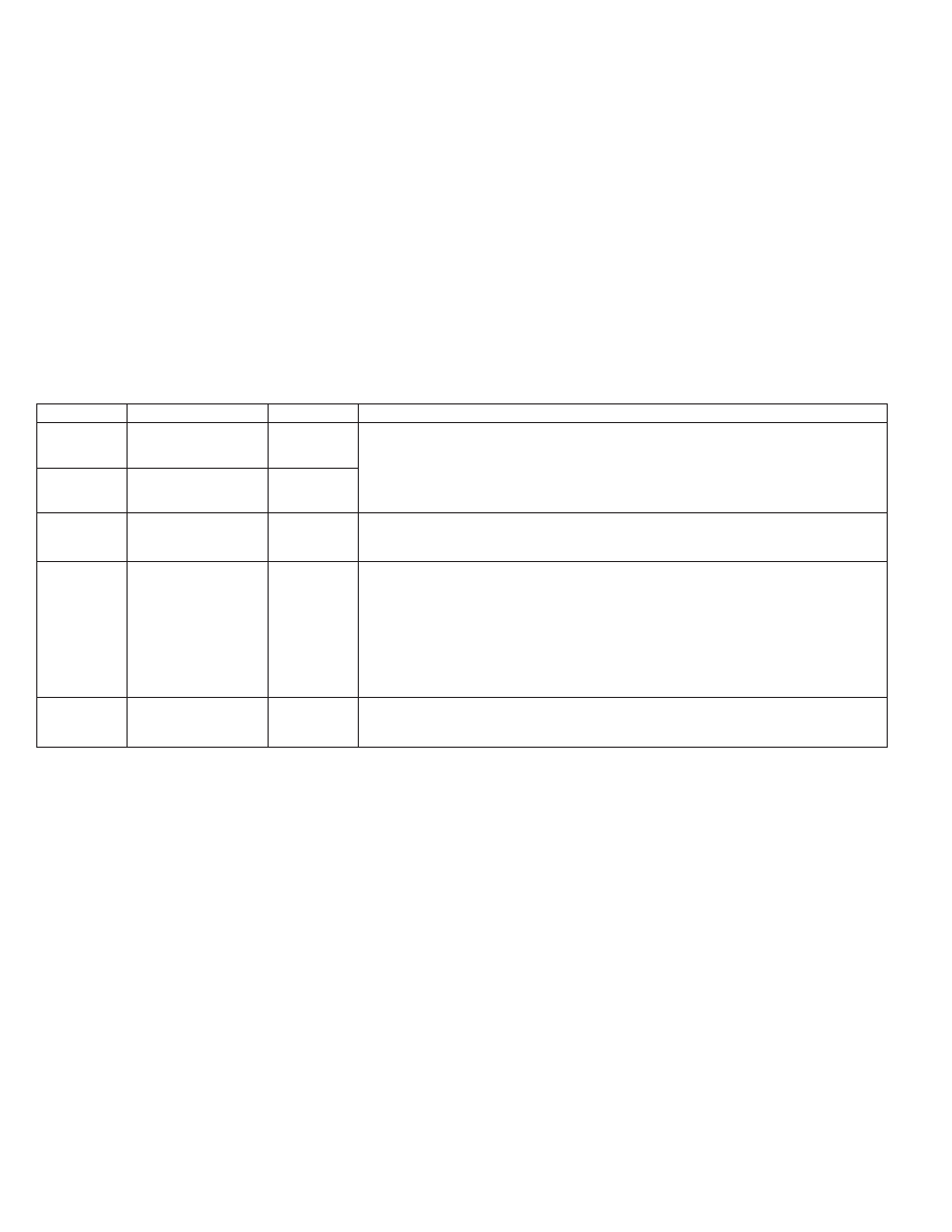
READY
POWER
FAULT
Status and action to be taken
嘷
○
嘷
○
○
The temperature detection circuit in the plug of the EVSE is malfunctioning.
Power Lamp status:
嘷
○
= Charge current reduced
●
= Charge stopped
Since the EVSE is restricting the charging current, it is recommended that you visit
a NISSAN certified LEAF dealer.
嘷
○
●
○
○
●
○
This trouble is caused by a malfunction of the EVSE internal circuits.
Stop using the EVSE immediately. It is recommended that you visit a NISSAN certi-
fied LEAF dealer.
○
嘷
○
○
For L1 & L2 EVSE:
This trouble may be caused by a miswired outlet. Check if the outlet, which the
EVSE is connected to, is correctly wired and installed according to the regulations/
standards. If the same indication continues after checking the outlet wiring, the
EVSE may have a malfunction. It is recommended that you visit a NISSAN certified
LEAF dealer.
For L1 EVSE:
The EVSE may have a malfunction. It is recommended that you visit a NISSAN cer-
tified LEAF dealer.
○
●
嘷
○
The EVSE detected leakage current or PWM signal error
Stop using the EVSE immediately. It is recommended that you visit a NISSAN certi-
fied LEAF dealer.
Charging
CH-55