Nissan Murano (2022 year). Manual in english - page 26


  Index      Manuals     Nissan Murano (2022 year). Manual in english


Search            copyright infringement  


Content      ..     24      25      26      27     ..


Nissan Murano (2022 year). Manual in english - page 26


WARNING

Be sure the engine and ignition switch
are off and that the parking brake is
engaged securely.

CAUTION

Be sure to use the correct socket to re-
move the spark plugs. An incorrect
socket can damage the spark plugs.

If replacement is required, it is recom-
mended that you visit a NISSAN dealer for
this service.

The air cleaner filter should not be cleaned
and reused. Replace it according to the
maintenance log shown in the "Mainte-
nance and schedules" section of this
manual.

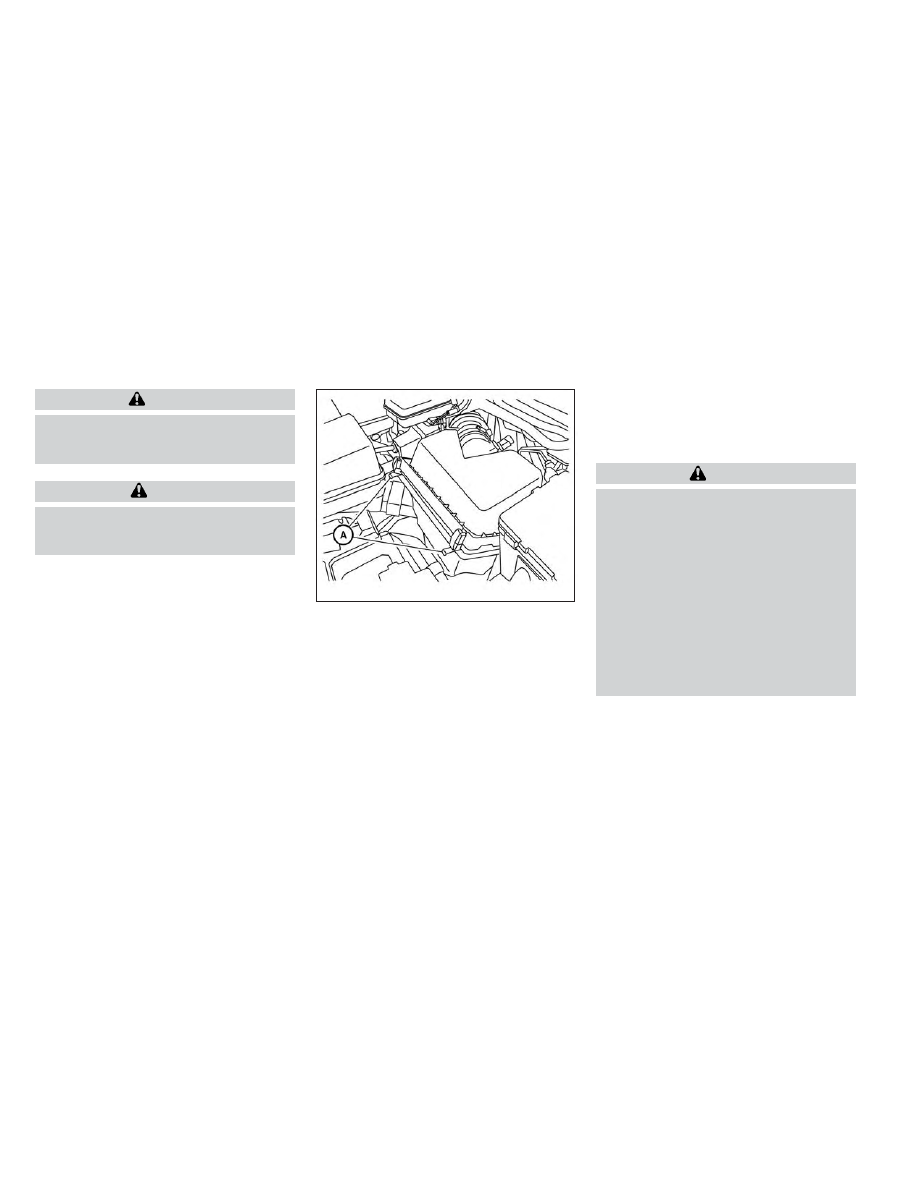
To remove the air cleaner filter:

1. Unlatch the retaining clips

O

A

.

2. Move the air cleaner cover upwards.

3. Remove the air cleaner filter. Wipe the

inside of the air cleaner filter housing
and the cover with a damp cloth, then
replace air cleaner filter.

NOTE:

After installing a new air cleaner filter,
make sure the air cleaner cover is seated
in the housing and latch the clips.

WARNING

Operating the engine with the air
cleaner removed can cause you or
others to be burned. The air cleaner
not only cleans the air, it stops the
flame if the engine backfires. If it isn't
there, and the engine backfires, you
could be burned. Do not drive with
the air cleaner removed, and be care-
ful when working on the engine with
the air cleaner removed.

Never pour fuel into the throttle body
or attempt to start the engine with
the air cleaner removed. Doing so
could result in serious injury.

LDI2553

AIR CLEANER

8-16

Do-it-yourself

-------------------------------------------------------------------------------------------------------------------------------------------------------------

IN-CABIN MICROFILTER

The in-cabin microfilter restricts the entry
of airborne dust and pollen particles and
reduces

some

objectionable

outside

odors. The filter is located behind the glove
box. For additional information, see the
“Maintenance and schedules” section of
this manual for change intervals.

If replacement is required, it is recom-
mended that you visit a NISSAN dealer for
this service.

CLEANING

If your windshield is not clear after using
the windshield-washer or if a wiper blade
chatters when running, wax or other mate-
rial may be on the blade or windshield.

Clean the outside of the windshield with a
washer solution or a mild detergent. Your
windshield is clean if beads do not form
when rinsing with clear water.

Clean each blade by wiping it with a cloth
soaked in a washer solution or a mild de-
tergent. Then rinse the blades with clear
water. If your windshield is still not clear
after cleaning the blades and using the
wiper, replace the blades.

CAUTION

Worn windshield wiper blades can
damage the windshield and impair
driver vision.

REPLACING

Replace the wiper blades if they are worn.

To replace the windshield wiper blades, fol-
low the procedure below:

1. Lift the wiper arm away from the

windshield.

2. Lift the release tab

O

A

.

3. Move the wiper blade

O

B

down and

remove.

4. Insert the new wiper blade onto the

wiper arm.

5. Push the release tab down until it clicks.

LDI2584

WINDSHIELD WIPER BLADES

Do-it-yourself

8-17

-------------------------------------------------------------------------------------------------------------------------------------------------------------

6. Push wiper on to windshield.

CAUTION

After wiper blade replacement, re-
turn the wiper arm to its original po-
sition; otherwise it may be damaged
when the hood is opened.

Make sure the wiper blades contact
the glass; otherwise the arms may be
damaged from wind pressure.

If you wax the surface of the hood, be care-
ful not to let wax get into the washer nozzle

O

D

. This may cause clogging or improper

windshield-washer operation. If wax gets
into the nozzle, remove it with a needle or
small pin

O

C

.

Rear window wiper blade

It is recommended that you visit a NISSAN
dealer if checking or replacement is
required.

LDI2731

8-18

Do-it-yourself

-------------------------------------------------------------------------------------------------------------------------------------------------------------

If the brakes do not operate properly, have
the brakes checked. It is recommended
that you visit a NISSAN dealer for this
service.

Self-adjusting brakes

Your vehicle is equipped with self-adjusting
brakes.

The front and rear disc-type brakes self-
adjust every time the brake pedal is
applied.

WARNING

Have your brake system checked if the
brake pedal height does not return to
normal. It is recommended that you
visit a NISSAN dealer for this service.

Brake pad wear indicators

The disc brake pads on your vehicle have
audible wear indicators. When a brake pad
requires

replacement,

a

high

pitched

scraping or screeching sound will be heard
when the vehicle is in motion. The noise will
be heard whether or not the brake pedal is
depressed. Have the brakes checked as
soon as possible if the wear indicator
sound is heard.

Under some driving or climate conditions,
occasional brake squeak, squeal or other
noise may be heard. Occasional brake
noise during light to moderate stops is nor-
mal and does not affect the function or
performance of the brake system.

Proper brake inspection intervals should
be followed.

For additional information re-

garding brake inspections, refer to the ap-
propriate maintenance schedule informa-
tion in the "Maintenance and schedules"
section of this manual.

If any electrical equipment does not oper-
ate, check for an open fuse.

Fuses are used in the passenger and en-
gine compartment. Spare fuses are pro-
vided and can be found in the passenger
compartment fuse box.

When installing a fuse make sure the fuse is
installed in the fuse box securely.

LDI2385

BRAKES

FUSES

Do-it-yourself

8-19

-------------------------------------------------------------------------------------------------------------------------------------------------------------

ENGINE COMPARTMENT

WARNING

Never use a fuse of higher or lower am-
perage rating than that specified on
the fuse box cover. This could damage
the electrical system or electronic con-
trol units or cause a fire.

If any electrical equipment does not come
on, check for an open fuse.

1. Be sure the ignition switch and the head-

light switch are OFF.

2. Open the engine hood.

3. Remove the fuse box cover by pushing

the tab and lifting the cover up.

4. Remove the fuse with the fuse puller.

The fuse puller is located in the center of
the

fuse

block

in

the

passenger

compartment.

5. If the fuse is open

O

A

, replace it with a

new fuse

O

B

.

6. If a new fuse also opens, have the elec-

trical system checked and repaired. It is
recommended that you visit a NISSAN
dealer for this service.

Fusible links

If any electrical equipment does not oper-
ate and the fuses are in good condition,
check the fusible links in the holder. If any of
the fusible links are melted, replace only
with Genuine NISSAN parts.

LDI2636

LDI0456

8-20

Do-it-yourself

-------------------------------------------------------------------------------------------------------------------------------------------------------------

For checking and replacing the fusible links,
it is recommended that you visit a NISSAN
dealer for this service.

PASSENGER COMPARTMENT

WARNING

Never use a fuse of higher or lower am-
perage rating than that specified on
the fuse box cover. This could damage
the electrical system or electronic con-
trol units or cause a fire.

If any electrical equipment does not oper-
ate, check for an open fuse.

NOTE:

The fuse box is located on the driver's
side of the instrument panel.

1. Be sure the ignition switch and the head-

light switch are OFF.

2. Pull down on fuse box cover

O

A

to

remove.

3. Locate the fuse that needs to be

replaced.

LDI2901

Do-it-yourself

8-21

-------------------------------------------------------------------------------------------------------------------------------------------------------------

4. Remove the fuse with the fuse puller

O

B

.

5. If the fuse is open

O

C

, replace it with an

equivalent good fuse

O

D

.

6. Push the fuse box cover to install.

If a new fuse also opens, have the electrical
system checked and repaired. It is recom-
mended that you visit a NISSAN dealer for
this service.

CAUTION

Be careful not to allow children to swal-
low the battery or removed parts.

NOTE:

Your vehicle may not be equipped with
all the fuses listed on the fuse label.

LDI2902

LDI2713

BATTERY REPLACEMENT

8-22

Do-it-yourself

-------------------------------------------------------------------------------------------------------------------------------------------------------------

NISSAN INTELLIGENT KEY®

Replace the battery in the Intelligent Key as
follows:

1. Remove the mechanical key from the

Intelligent Key.

2. Insert a small flathead screwdriver

O

A

into the slit

O

B

of the corner and twist it

to separate the upper part from the
lower part. Place a cloth over the screw-
driver to protect the casing.

LDI2001

LDI2637

Do-it-yourself

8-23

-------------------------------------------------------------------------------------------------------------------------------------------------------------

3. Replace the battery with a new one.

Recommended

battery:

CR2032

or

equivalent.

• Do not touch the internal circuit and

electric terminals as doing so could
cause a malfunction.

• Hold the battery by the edges. Holding

the battery across the contact points
will seriously deplete the storage
capacity.

• Make sure that the + side faces the

bottom of the lower part.

4. Close the lid securely as illustrated with

O

C

and

O

D

.

5. Operate the buttons to check the

operation.

If you need assistance with replacement, it
is recommended that you visit a NISSAN
dealer for this service.

FCC Notice:

For USA:
This device complies with Part 15 of the
FCC Rules. Operation is subject to the fol-
lowing two conditions: (1) This device
may not cause harmful interference, and
(2) this device must accept any interfer-
ence received, including interference
that may cause undesired operation.

Note:

Changes or modifications not expressly
approved by the party responsible for
compliance could void the user’s author-
ity to operate the equipment.

For Canada:
This

device

contains

licence-exempt

transmitter(s)/receiver(s) that comply
with Innovation, Science and Economic
Development Canada’s licence-exempt
RSS(s). Operation is subject to the fol-
lowing two conditions: (1) This device
may not cause interference. (2) This de-
vice must accept any interference, in-
cluding interference that may cause un-
desired operation of the device.

8-24

Do-it-yourself

-------------------------------------------------------------------------------------------------------------------------------------------------------------

HEADLIGHTS

For additional information on headlight
bulb replacement, refer to the instructions
outlined in this section.

Replacing the LED headlight bulb

If LED headlight bulb replacement is re-
quired, it is recommended that you visit a
NISSAN dealer for this service.

FOG LIGHTS (if so equipped)

For additional information on fog light bulb
replacement, refer to the instructions out-
lined in this section.

Replacing the LED fog light bulb

If LED fog light bulb replacement is re-
quired, it is recommended that you visit a
NISSAN dealer for this service.

EXTERIOR AND INTERIOR LIGHTS

Item

Wattage (W)

Bulb No.

Headlight assembly*

High

Low

Turn

Side marker

Park/Daytime running

Fog lights (if so equipped)*

Door mirror turn signal light (if so equipped)*

Map light*

Courtesy light*

Personal light*

Vanity mirror light*

2

SAE 37

Glove box light*

1.4

Cargo light*

5

High-mounted stop light*

Rear combination light*

Tail/Stop

Turn

Rear side marker

Backup (reversing) light assembly*

Backup

Tail/Stop

License plate light*

5

W5W

* It is recommended that you visit a NISSAN dealer for assistance.

Always check with the Parts Department at a NISSAN dealer for the latest parts
information.

LIGHTS

Do-it-yourself

8-25

-------------------------------------------------------------------------------------------------------------------------------------------------------------

1.

Map light

2

Headlight assembly

3

Personal light

4.

Door mirror turn signal light (if so
equipped)

5.

Fog light (if so equipped)

6.

High-mounted stop light

7.

License plate light

8.

Backup (reversing) light assembly

9.

Rear combination light

10.

Cargo light

11.

Daytime running light

Replacement procedures

All other lights are either type A, B, C or D.
When replacing a bulb, first remove the
lens, lamp and/or cover.

Indicates bulb removal

Indicates bulb installation

LDI3332

WDI0263

8-26

Do-it-yourself

-------------------------------------------------------------------------------------------------------------------------------------------------------------

If you have a flat tire, see “Flat tire”
(P. 6-3).

TIRE PRESSURE

Tire Pressure Monitoring System
(TPMS)

WARNING

Radio waves could adversely af-
fect electric medical equipment.
Those who use a pacemaker
should contact the electric medi-
cal equipment manufacturer for
the possible influences before
use.

This vehicle is equipped with the Tire
Pressure Monitoring System (TPMS).
It monitors tire pressure of all tires
except the spare. When the low tire
pressure warning light is lit and the
“Tire Pressure Low - Add Air” warning
appears in the vehicle information
display, one or more of your tires is
significantly

under-inflated.

If

equipped, the system also displays
pressure of all tires (except the spare
tire) on the display screen by send-
ing a signal from a sensor that is
installed in each wheel.

The TPMS will activate only when the
vehicle is driven at speeds above 16
mph (25 km/h). Also, this system
may not detect a sudden drop in tire
pressure (for example a flat tire while
driving).

For additional information, see “Low
tire pressure warning light” (P. 2-11),
“Tire Pressure Monitoring System
(TPMS)” (P. 5-5) and ““Flat tire” (P. 6-3).

Tire inflation pressure

Check the tire pressures (including
the spare) often and always prior to
long distance trips. The recom-
mended tire pressure specifications
are shown on the F.M.V.S.S./C.M.V.S.S.
certification label or the Tire and
Loading Information label under the

“Cold Tire Pressure” heading. The Tire
and Loading Information label is af-
fixed to the driver side center pillar.
Tire pressures should be checked
regularly because:

• Most tires naturally lose air over

time.

• Tires can lose air suddenly when

driven over potholes or other ob-
jects or if the vehicle strikes a curb
while parking.

The

tire

pressures

should

be

checked when the tires are cold. The
tires are considered COLD after the
vehicle has been parked for 3 or
more hours, or driven less than 1 mile
(1.6 km) at moderate speeds.

The TPMS with Easy-Fill Tire Alert
provides visual and audible signals
outside the vehicle for inflating tires
to the recommended COLD tire
pressure. For additional information,
see “TPMS with Easy-Fill Tire Alert”
(P. 5-8).

WHEELS AND TIRES

Do-it-yourself

8-27

-------------------------------------------------------------------------------------------------------------------------------------------------------------

Incorrect tire pressure, including
under inflation, may adversely af-
fect tire life and vehicle handling.

WARNING

Improperly inflated tires can
fail suddenly and cause an
accident.

The Gross Vehicle Weight Rat-
ing (GVWR) is located on the
F.M.V.S.S./C.M.V.S.S.

certifica-

tion label. The vehicle weight
capacity is indicated on the Tire
and Loading Information label.
Do not load your vehicle be-
yond this capacity. Overloading
your vehicle may result in re-
duced tire life, unsafe operating
conditions due to premature
tire failure, or unfavorable han-
dling characteristics and could
also lead to a serious accident.
Loading beyond the specified
capacity may also result in fail-
ure

of

other

vehicle

components.

Before taking a long trip, or
whenever you heavily load your
vehicle, use a tire pressure
gauge to ensure that the tire
pressures are at the specified
level.

For additional information re-
garding tires, refer to “Impor-
tant Tire Safety Information”
(US) or “Tire Safety Information”
(Canada) in the Warranty Infor-
mation Booklet.

8-28

Do-it-yourself

-------------------------------------------------------------------------------------------------------------------------------------------------------------

Tire and Loading Information
label

1

Seating capacity: The maximum
number of occupants that can
be seated in the vehicle.

2

Tire size - see “Tire labeling”
(P. 8-31).

3

Cold tire pressure: Inflate the tires
to this pressure when the tires
are cold. Tires are considered
COLD after the vehicle has been

parked for 3 or more hours, or
driven less than 1 mile (1.6 km) at
moderate speeds. The recom-
mended cold tire inflation is set
by the manufacturer to provide
the best balance of tire wear, ve-
hicle handling, driveability, tire
noise, etc., up to the vehicle's
GVWR.

4

Original tire size: The size of the
tires originally installed on the ve-
hicle at the factory.

5

Spare tire size.

6

Vehicle load limit: see “Vehicle
loading information” (P. 10-15).

LDI2737

Do-it-yourself

8-29

-------------------------------------------------------------------------------------------------------------------------------------------------------------

Checking tire pressure

1. Remove the valve stem cap from

the tire.

2. Press

the

pressure

gauge

squarely onto the valve stem. Do
not press too hard or force the
valve stem sideways, or air will es-
cape. If the hissing sound of air
escaping from the tire is heard
while checking the pressure, re-
position the gauge to eliminate
this leakage.

3. Remove the gauge.

4. Read the tire pressure on the

gauge stem and compare to the
specification shown on the Tire
and Loading Information label.

5. Add air to the tire as needed. If too

much air is added, press the core
of the valve stem briefly with the
tip of the gauge stem to release
pressure. Recheck the pressure
and add or release air as needed.

6. Install the valve stem cap.

7. Check the pressure of all other

tires, including the spare.

Size

Cold Tire Infla-
tion Pressure

Front and Rear
Original Tire:
235/65R18

33 psi, 230 kPa

Front and Rear
Original Tire:
235/55R20

35 psi, 240 kPa

Spare Tire:
T165/90D18

60 psi, 420 kPa

LDI0393

8-30

Do-it-yourself

-------------------------------------------------------------------------------------------------------------------------------------------------------------

TIRE LABELING

Federal law requires tire manufac-
turers to place standardized infor-
mation on the sidewall of all tires.
This information identifies and de-
scribes the fundamental character-
istics of the tire and also provides the
Tire Identification Number (TIN) for
safety standard certification. The TIN
can be used to identify the tire in
case of a recall.

O

1

Tire size (example: P215/65R15

95H)

1. P: The “P” indicates the tire is de-

signed for passenger vehicles (not
all tires have this information).

2. Three-digit number (215): This

number gives the width in milli-
meters of the tire from sidewall
edge to sidewall edge.

3. Two-digit number (65): This num-

ber, known as the aspect ratio,
gives the tire's ratio of height to
width.

4. R: The “R” stands for radial.

5. Two-digit number (15): This num-

ber is the wheel or rim diameter in
inches.

WDI0394

Example

WDI0395

Example

Do-it-yourself

8-31

-------------------------------------------------------------------------------------------------------------------------------------------------------------


Content      ..     24      25      26      27     ..