Nissan Pathfinder (2022 year). Manual in english - page 18
When the camera is first activated with the
bird’s-eye view in the display, a red icon (if so
equipped) will flash on the screen. This in-
dicates that the sonar system is activated.
For additional information, see “Front and
Rear Sonar System (RSS)” (P. 5-183).
Available views
WARNING
•
The distance guide lines and the ve-
hicle width lines should be used as a
reference only when the vehicle is on
a paved, level surface. The apparent
distance viewed on the monitor may
be different than the actual distance
between the vehicle and displayed
objects.
•
Use the displayed lines and the
bird’s-eye view as a reference. The
lines and the bird’s-eye view are
greatly affected by the number of oc-
cupants, cargo, fuel level, vehicle po-
sition,
road
condition
and
road
grade.
•
If the tires are replaced with different
sized tires, the predicted course lines
and the bird's-eye view may be dis-
played incorrectly.
•
When driving the vehicle up a hill, ob-
jects viewed in the monitor are fur-
ther than they appear. When driving
the vehicle down a hill, objects
viewed in the monitor are closer than
they appear.
•
Objects in the rear view will appear
visually opposite compared to when
viewed in the monitor and outside
mirrors.
•
Use the mirrors or actually look to
properly judge distances to other
objects.
•
On a snow-covered or slippery road,
there may be a difference between
the predicted course lines and the
actual course line.
•
The vehicle width and predicted
course lines are wider than the actual
width and course.
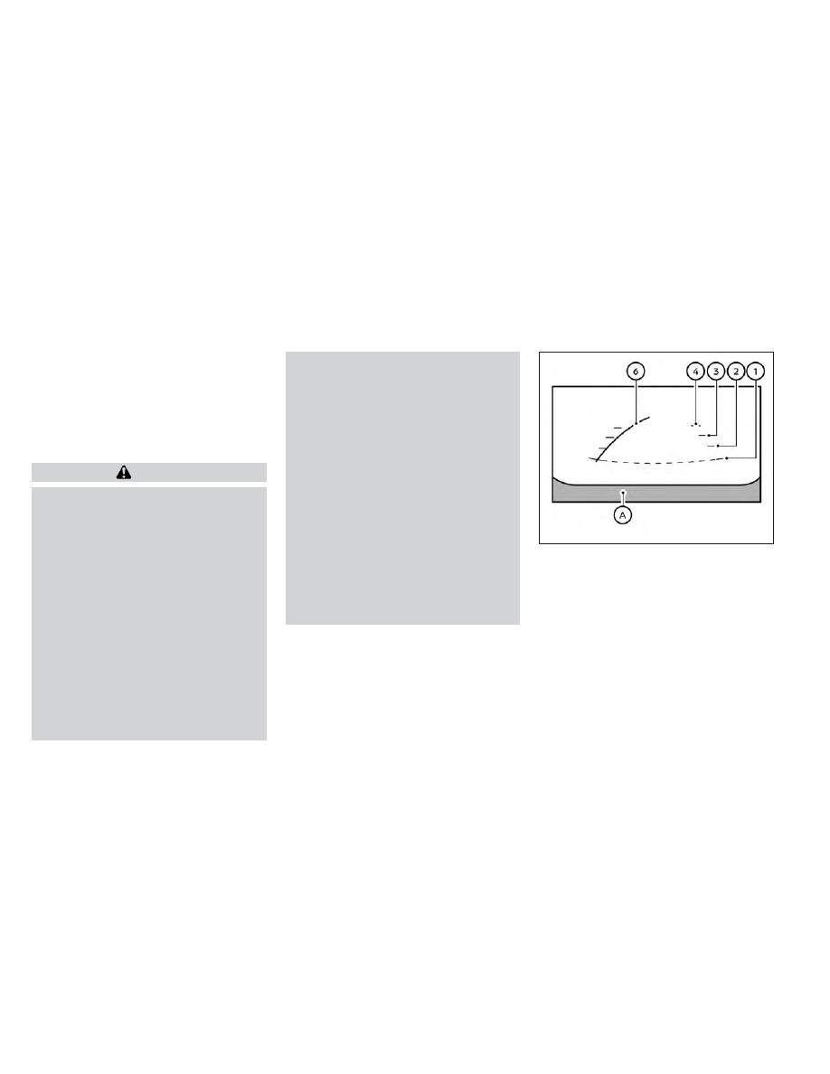
Front and rear view
Guiding lines that indicate the approximate
vehicle width and distance to objects with
reference to the vehicle body line
O
A
are
displayed on the monitor.
Distance guide lines
Indicate distances from the vehicle body:
• Red line
O
1
: approximately 1.5 ft (0.5 m)
• Yellow line
O
2
: approximately 3 ft (1 m)
• Green line
O
3
: approximately 7 ft (2 m)
• Green line
O
4
: approximately 10 ft (3 m)
(if so equipped)
LHA5437
Front view
4-12
Monitor, climate, audio, phone and voice recognition systems