Nissan Qashqai (2022 year). Manual in english - page 15
JVH0664X
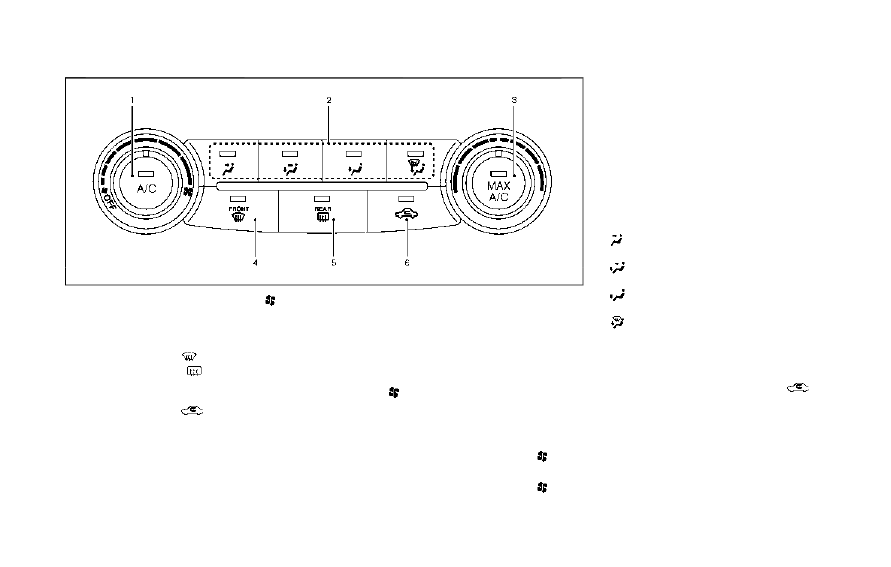
1.
A/C button/Fan speed control
dial
2.
Air flow control buttons
3.
MAX A/C button/Temperature control
dial
4.
Front defroster
button
5.
Rear defroster
button (See “Rear
window and outside mirror defroster
switch” (P.2-51).)
6.
Air recirculation
button
MANUAL AIR CONDITIONER AND
HEATER
Controls
Turning system on/off:
To turn on the system, turn the fan speed
control
dial out of the OFF position.
Turn the dial counterclockwise to the OFF
position to turn off the system.
Fan speed control:
Turn the fan speed control
dial
clockwise to increase the fan speed.
Turn the fan speed control
dial
counterclockwise to decrease the fan
speed.
Temperature control:
Turn the temperature control dial to set
the desired temperature. Turn the dial
between the middle and the right posi-
tion to select the hot temperature. Turn
the dial between the middle and the left
position to select the cool temperature.
Air flow control:
Push one of the air flow control buttons
to select the air flow outlets.
— Air flows mainly from center and side
ventilators.
— Air flows mainly from center and side
ventilators and foot outlets.
— Air flows mainly from the foot outlet
and partly from the defroster.
— Air flows mainly from the defroster
and foot outlets.
Air intake control:
The air intake control mode will change
each time the air recirculation
button
is pushed.
.
When the indicator light is turned on,
the air recirculates inside the vehicle.
.
When the indicator light is turned off,
the air flow is drawn from outside the
vehicle.
Monitor, heater, air conditioner, audio and phone systems
4-27