Nissan Titan (2022 year). Manual in english - page 11
The hill descent control indicator light
blinks if the switch is on and all conditions
for system activation are not met or if the
system becomes disengaged for any
reason.
To turn off the hill descent control system,
push the switch to the OFF position.
For additional information, see “Hill descent
control system ON indicator light” (P. 2-18)
and “Hill descent control system” (P. 5-122).
The E-Lock system can help provide added
traction if the vehicle is stuck or becoming
stuck.
To activate the E-Lock system:
• the 4WD switch must be in the 4LO posi-
tion (4-wheel drive vehicles),
• the vehicle must be stopped or moving at
4 mph (7 km/h) or less, and
• the E-Lock system switch must be
turned ON.
When the E-Lock system switch is turned
ON, the indicator light will flash until the
system engages. However, if all operation
conditions listed above are not met or the
system becomes disengaged, the indica-
tor light will continue to flash.
The Anti-lock Braking System (ABS) system
is disabled and the ABS light illuminates
when the E-Lock system is on.
For additional information, see “Electronic
locking rear differential (E-Lock) system”
(P. 5-113) for further explanation and system
limitations.
WARNING
•
Never leave the E-Lock system ON
when driving on paved or hard-
surfaced roads. Turning the vehicle
may result in the rear wheels slipping
and result in an accident and per-
sonal injury. After using the E-Lock
system to free the vehicle, turn the
system OFF.
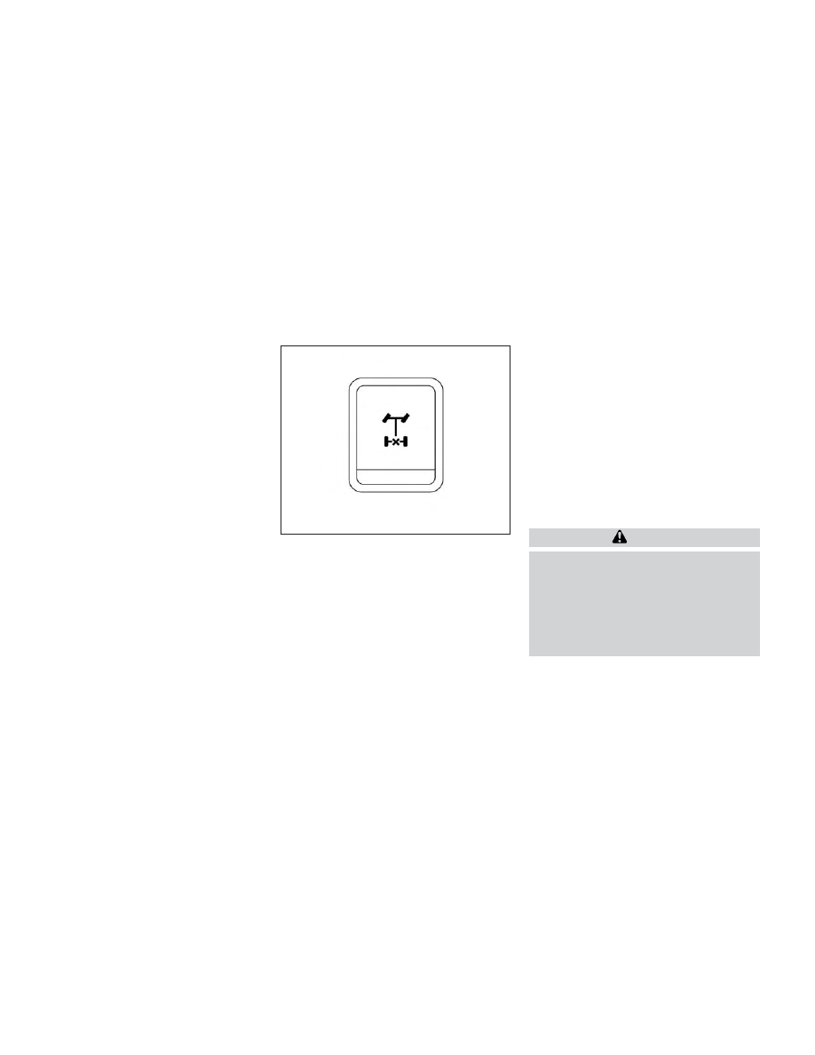
LIC4341
ELECTRONIC LOCKING REAR
DIFFERENTIAL (E-Lock) SYSTEM
SWITCH (if so equipped)
2-60
Instruments and controls