Nissan Versa (2022 year). Manual in english - page 18

SYSTEM MALFUNCTION
• Do not attach metallic objects near the
sensor area (brush guard, etc.). This could
If the I-FCW system malfunctions, it will be
cause failure or malfunction.
turned off automatically, a chime will
sound, the AEB with Pedestrian Detection
• Do not alter, remove or paint the front
system warning light (orange) will illumi-
bumper. Before customizing or restoring
nate and the warning message [Malfunc-
the front bumper, it is recommended that
tion] will appear in the vehicle information
you visit a NISSAN dealer.
display (if so equipped).
Radio frequency statement
Action to take
For USA
If the warning light (orange) comes on, stop
the vehicle in a safe location, turn the en-
FCC ID OAYARS4B
gine off and restart the engine. If the
This device complies with Part 15 of the
warning light continues to illuminate, have
FCC Rules. Operation is subject to the fol-
the I-FCW system checked. It is recom-
LSD3534
lowing two conditions:
mended that you visit a NISSAN dealer for
SYSTEM MAINTENANCE
1. This device may not cause harmful in-
this service.
A is located behind the lower
terference, and
grille of the front bumper.
2. This device must accept any interfer-
To keep the system operating properly, be
ence received, including interference
sure to observe the following:
that may cause undesired operation.
• Always keep the sensor area of the front
bumper clean.
• Do not strike or damage the areas
around the sensor.
• Do not cover or attach stickers or similar
objects on the front bumper near the
sensor area. This could cause failure or
malfunction.
5-108
Starting and driving
FCC Warning
This equipment should be installed and
Le présent appareil est conforme aux
operated with minimum distance of 20
CNR d'Industrie Canada applicables aux
Changes or modifications not expressly
cm between the radiator and your body.
appareils radio exempts de licence.
approved by the party responsible for
L'exploitation est autorisée aux deux
compliance could void the user’s author-
The transmitter must not be co-located
conditions suivantes:
ity to operate the equipment.
or operating in conjunction with any
other antenna or transmitter.
1. L'appareil ne doit pas produire de
This equipment has been tested and
brouillage, et
found to comply with the limits for a
For Canada
Class A digital device, pursuant to Part 15
2. L'utilisateur de l'appareil doit ac-
Model: ARS4-B
of the FCC Rules. These limits are de-
cepter tout brouillage radioélectrique
signed to provide reasonable protection
IC: 4135A-ARS4B
subi, même si le brouillage est suscep-
against harmful interference when the
FCC ID: OAYARS4B
tible
d'en
compromettre le
equipment is operated in a commercial
fonctionnement.
This device complies with Industry
environment. This equipment generates,
Canada licence-exempt RSS standard(s).
Radio frequency radiation exposure
uses, and can radiate radio frequency
Operation is subject to the following two
information:
energy and, if not installed and used in
conditions:
accordance with the instruction manual,
This equipment complies with FCC and IC
may cause harmful interference to radio
1. This device may not cause interfer-
radiation exposure limits set forth for an
communications. Operation of this
ence, and
uncontrolled environment.
equipment in a residential area is likely
2. This device must accept any interfer-
This equipment should be installed and
to cause harmful interference in which
operated with minimum distance of 30
ence received, including interference
case the user will be required to correct
that may cause undesired operation
cm between the radiator and your body.
the interference at his own expense.
of the device.
This transmitter must not be co-located
Radio frequency radiation exposure
or operating in conjunction with any
information:
other antenna or transmitter.
This equipment complies with FCC radia-
tion exposure limits set forth for an un-
controlled environment.
Starting and driving
5-109
INTELLIGENT DRIVER ALERTNESS
(I-DA) (if so equipped)
Cet équipement est conforme aux lim-
The I-DA system helps alert the driver if the
WARNING
ites d'exposition aux rayonnements IC
system detects a lack of attention or driv-
établies pour un environnement non
Failure to follow the warnings and in-
ing fatigue.
contrôlé.
structions for proper use of the I-DA
The system monitors driving style and
system could result in serious injury or
Cet équipement doit être installé et
steering behavior over a period of time,
utilisé avec un minimum de 30 cm de
death.
and it detects changes from the normal
distance entre la source de rayonnement
•
The I-DA system is only a warning to
pattern. If the system detects that driver
et votre corps.
inform the driver of a potential lack
attention is decreasing over a period of
of driver attention or drowsiness. It
time, the system uses audible and visual
FCC Notice
will not steer the vehicle or prevent
warnings to suggest that the driver take a
Changes or modifications not expressly
loss of control.
break.
approved by the party responsible for
•
The I-DA system does not detect and
compliance could void the user’s author-
provide an alert of the driver’s lack of
ity to operate the equipment.
attention or fatigue in every
situation.
•
It is the driver’s responsibility to:
•
stay alert,
•
drive safely,
•
keep the vehicle in the traveling
lane,
•
be in control of the vehicle at all
times,
•
avoid driving when tired,
•
avoid distractions (texting, etc.).
5-110
Starting and driving
The system resets and starts reassessing
driving style and steering behavior when
the ignition switch is cycled from ON to OFF
and back on.
LSD3545
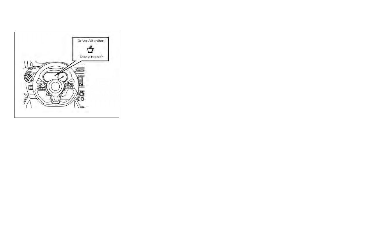
INTELLIGENT DRIVER ALERTNESS
SYSTEM OPERATION
If the system detects driver fatigue or that
driver attention is decreasing, the mes-
sage “Take a break?” appears in the vehicle
information display and a chime sounds
when the vehicle is driven at speeds above
37 mph (60 km/h).
The system continuously monitors driver
attention and can provide multiple warn-
ings per trip.
Starting and driving
5-111

Perform the following steps to enable or
disable the I-DA system.
1. Press the
button until “Settings” dis-
plays in the vehicle information display
and press the OK button. Use the
button to select “Driver Assistance.” Then
press the OK button.
2. Select “Driver Attention Alert” and press
the OK button.
NOTE:
The setting will be retained even if the
engine is restarted.
LSD4105
HOW TO ENABLE/DISABLE THE
INTELLIGENT DRIVER ALERTNESS
(I-DA) SYSTEM
5-112
Starting and driving

INTELLIGENT DRIVER ALERTNESS
Action to take
(I-DA) SYSTEM LIMITATIONS
Stop the vehicle in a safe location, place the
vehicle in P (Park) position, turn the engine
WARNING
off and restart the engine. If the system
warning message continues to appear,
Listed below are the system limitations
have the system checked. It is recom-
for the I-DA system. Failure to operate
mended that you visit a NISSAN dealer for
the vehicle in accordance with these
this service.
system limitations could result in seri-
ous injury or death.
•
The I-DA system may not operate
properly and may not provide an
alert in the following conditions:
- Poor road conditions such as an
LSD3563
uneven road surface or pot holes.
- Strong side wind.
System malfunction
- If you have adopted a sporty driv-
If the Intelligent Driver Alertness
system
ing style with higher cornering
malfunctions, the system warning mes-
speeds or higher rates of
sage will appear in the vehicle information
acceleration.
display and the function will be stopped
- Frequent lane changes or
automatically.
changes to vehicle speed.
•
The I-DA system will not provide an
alert in the following conditions:
- Vehicle speeds lower than 37 mph
(60 km/h).
- Short lapses of attention.
- Instantaneous distractions such
as dropping an object.
Starting and driving
5-113

BREAK-IN SCHEDULE
FUEL EFFICIENT DRIVING TIPS
Follow these easy-to-use Fuel Efficient
• Recirculating the cool air in the cabin
CAUTION
Driving Tips to help you achieve the most
when the A/C is on reduces cooling
During the first 1,200 miles (2,000 km),
fuel economy from your vehicle.
load.
follow these recommendations to ob-
1.
Use Smooth Accelerator and Brake
4.
Drive at Economical Speeds and
tain maximum engine performance
Pedal Application
Distances
and ensure the future reliability and
• Avoid rapid starts and stops.
• Observing the speed limit and not ex-
economy of your new vehicle. Failure to
• Use smooth, gentle accelerator and
ceeding 60 mph (97 km/h) (where le-
follow these recommendations may
brake application whenever possible.
gally allowed) can improve fuel effi-
result in shortened engine life and re-
ciency due to reduced aerodynamic
duced engine performance.
• Maintain constant speed while com-
drag.
muting and coast whenever possible.
•
Avoid driving for long periods at constant
• Maintaining a safe following distance
speed, either fast or slow, and do not run
2.
Maintain Constant Speed
behind other vehicles reduces unnec-
the engine over 4,000 rpm.
• Look ahead to try and anticipate and
essary braking.
•
Do not accelerate at full throttle in any
minimize stops.
• Safely monitoring traffic to anticipate
gear.
• Synchronizing your speed with traffic
changes in speed permits reduced
•
Avoid quick starts.
lights allows you to reduce your num-
braking and smooth acceleration
•
Avoid hard braking as much as possible.
ber of stops.
changes.
• Maintaining a steady speed can mini-
• Select a gear range suitable to road
mize red light stops and improve fuel
conditions.
efficiency.
5.
Use Cruise Control
3.
Use Air Conditioning (A/C) at Higher
• Using cruise control during highway
Vehicle Speeds
driving helps maintain a steady speed.
• Below 40 mph (64 km/h), it is more
• Cruise control is particularly effective
efficient to open windows to cool the
in providing fuel savings when driving
vehicle due to reduced engine load.
on flat terrains.
• Above 40 mph (64 km/h), it is more
efficient to use A/C to cool the vehicle
due to increased aerodynamic drag.
5-114
Starting and driving
INCREASING FUEL ECONOMY
6. Plan for the Shortest Route
10. Keeping your Vehicle Cool
•
Keep your engine tuned up.
• Utilize a map or navigation system to
•
Park your vehicle in a covered parking
•
Follow the recommended scheduled
determine the best route to save time.
area or in the shade whenever
maintenance.
possible.
•
Keep the tires inflated to the correct pres-
7. Avoid Idling
•
When entering a hot vehicle, opening
sure. Low tire pressure increases tire
• Shutting off your engine when safe for
the windows will help to reduce the
wear and lowers fuel economy.
stops exceeding 30-60 seconds saves
inside temperature faster, resulting in
•
Keep the wheels in correct alignment. Im-
fuel and reduces emissions.
reduced demand on your A/C system.
proper alignment increases tire wear and
8.
Buy an Automated Pass for Toll Roads
lowers fuel economy.
• Automated passes permit drivers to
•
Use the recommended viscosity engine
use special lanes to maintain cruising
oil. For additional information, see “Engine
speed through the toll and avoid stop-
oil and oil filter recommendations”
ping and starting.
(P. 10-2).
9.
Winter Warm Up
• Limit idling time to minimize impact to
fuel economy.
• Vehicles typically need no more than
30 seconds of idling at start-up to ef-
fectively circulate the engine oil before
driving.
• Your vehicle will reach its ideal operat-
ing temperature more quickly while
driving versus idling.
Starting and driving
5-115

PARKING/PARKING ON HILLS
•
Do not leave children unattended in-
side the vehicle. They could unknow-
ingly activate switches or controls or
make the vehicle move. Unattended
children could become involved in
serious accidents.
•
To help avoid risk of injury or death
through unintended operation of the
vehicle and/or its systems, do not
leave children, people who require
the assistance of others or pets unat-
tended in your vehicle. Additionally,
the temperature inside a closed ve-
hicle on a warm day can quickly be-
SSD0488
come high enough to cause a signifi-
cant risk of injury or death to people
WARNING
•
Safe parking procedures require that
and pets.
both the parking brake be set and the
•
Do not stop or park the vehicle over
transmission placed into P (Park) or
1.
Firmly apply the parking brake.
flammable materials such as dry
in an appropriate gear for manual
grass, waste paper or rags. They may
2.
M/T models:
transmission (M/T) models. Failure to
ignite and cause a fire.
do so could cause the vehicle to
Place the shift lever in the R (Reverse)
move unexpectedly or roll away and
position. When parking on an uphill
result in an accident. Make sure the
grade, place the shift lever in 1st gear.
shift lever has been pushed as far
Continuously Variable Transmission
forward as it can go and cannot be
models:
moved without depressing the foot
brake pedal.
Move the shift lever into the P (Park)
•
Never leave the engine running while
position.
the vehicle is unattended.
5-116
Starting and driving
POWER STEERING
3. To help prevent the vehicle from rolling
erations that could cause the power steer-
WARNING
into traffic when parked on an incline, it
ing system to overheat.
is a good practice to turn the wheels as
• If the engine is not running or is
You may hear a sound when the steering
illustrated.
turned off while driving, the power
wheel is operated quickly. However, this is
1
:
assist for the steering will not work.
not a malfunction.
Steering will be harder to operate.
Turn the wheels into the curb and move
If the power steering warning light illumi-
the vehicle forward until the curb side
• When the power steering warning
nates while the engine is running, it may
wheel gently touches the curb.
light illuminates with the engine run-
indicate the power steering system is not
ning, there will be no power assist for
2
:
functioning properly and may need servic-
the steering. You will still have control
Turn the wheels away from the curb and
ing. Have the power steering system
of the vehicle, but the steering will be
move the vehicle back until the curb side
checked. It is recommended that you visit a
harder to operate. Have the power
wheel gently touches the curb.
NISSAN dealer for this service.
steering system checked. It is recom-
• HEADED UPHILL OR DOWNHILL, NO CURB
mended that you visit a NISSAN
When the power steering warning light illu-
3
:
dealer for this service.
minates with the engine running, there will
Turn the wheels toward the side of the
be no power assist for the steering, but you
The power steering system is designed to
road so the vehicle will move away from
will still have control of the vehicle. At this
provide power assist while driving to oper-
the center of the road if it moves.
time, greater steering effort is required to
ate the steering wheel with light force.
operate the steering wheel, especially in
4. Place the ignition switch in the LOCK po-
When the steering wheel is operated re-
sharp turns and at low speeds.
sition and remove the key.
peatedly or continuously while parking or
For additional information, see
“Power
driving at a very low speed, the power as-
steering warning light” (P. 2-20).
sist for the steering wheel will be reduced.
This is to prevent overheating of the power
steering system and protect it from getting
damaged. While the power assist is re-
duced, steering wheel operation will be-
come heavy. When the temperature of the
power steering system goes down, the
power assist level will return to normal.
Avoid repeating such steering wheel op-
Starting and driving
5-117
BRAKE SYSTEM
The brake system has two separate hy-
Parking brake break-in
WARNING
draulic circuits. If one circuit malfunctions,
Break in the parking brake shoes whenever
you will still have braking at two wheels.
• While driving on a slippery surface,
the stopping effect of the parking brake is
be careful when braking, accelerat-
BRAKE PRECAUTIONS
weakened or whenever the brake shoes
ing or downshifting. Abrupt braking
and/or drums/rotors are replaced, in order
or accelerating could cause the
to assure the best brake performance.
Vacuum assisted brakes
wheels to skid and result in an
The brake booster aids braking by using
accident.
This procedure is described in the vehicle
service manual. It is recommended that
engine vacuum. If the engine stops, you
• If the engine is not running or is
can stop the vehicle by depressing the
turned off while driving, the power
you visit a NISSAN dealer for this service.
brake pedal. However, greater foot pres-
assist for the brakes will not work.
ANTI-LOCK BRAKING SYSTEM (ABS)
sure on the brake pedal will be required to
Braking will be harder.
stop the vehicle and stopping distance will
WARNING
be longer.
Wet brakes
•
The ABS is a sophisticated device, but
When the vehicle is washed or driven
Using the brakes
it cannot prevent accidents resulting
through water, the brakes may get wet. As
from careless or dangerous driving
Avoid resting your foot on the brake pedal
a result, your braking distance will be lon-
while driving. This will overheat the brakes,
ger and the vehicle may pull to one side
techniques. It can help maintain ve-
hicle control during braking on slip-
wear out the brake pads faster, and reduce
during braking.
gas mileage.
pery surfaces. Remember that stop-
To dry the brakes, drive the vehicle at a safe
ping distances on slippery surfaces
To help reduce brake wear and to prevent
speed while lightly pressing the brake
will be longer than on normal sur-
the brakes from overheating, reduce speed
pedal to heat up the brakes. Do this until
faces even with ABS. Stopping dis-
and downshift to a lower gear before going
the brakes return to normal. Avoid driving
tances may also be longer on rough,
down a slope or long grade. Overheated
the vehicle at high speeds until the brakes
gravel or snow covered roads, or if
brakes may reduce braking performance
function correctly.
you are using tire chains. Always
and could result in loss of vehicle control.
maintain a safe distance from the ve-
hicle in front of you. Ultimately, the
driver is responsible for safety.
5-118
Starting and driving

Using the system
instrument panel. The brake system then
• Tire type and condition may also af-
operates normally but without anti-lock
fect braking effectiveness.
Depress the brake pedal and hold it down.
assistance.
- When replacing tires, install the
Depress the brake pedal with firm steady
specified size of tires on all four
pressure, but do not pump the brakes. The
If the ABS warning light illuminates during
wheels.
Anti-lock Braking System will operate to
the self-test or while driving, have the ve-
prevent the wheels from locking up. Steer
hicle checked. It is recommended that you
- When installing a spare tire, make
the vehicle to avoid obstacles.
visit a NISSAN dealer for this service.
sure that it is the proper size and
type as specified on the Tire and
WARNING
Normal operation
Loading Information label. For ad-
ditional information, see “Tire and
The Anti-lock Braking System (ABS) oper-
Do not pump the brake pedal. Doing so
Loading Information
label”
ates at speeds above 3 - 6 mph (5 - 10
may result in increased stopping
(P. 8-30).
km/h). The speed varies according to road
distances.
- For additional information, see
conditions.
“Wheels and tires” (P. 8-27).
Self-test feature
When the ABS senses that one or more
The ABS controls the brakes so the wheels
wheels are close to locking up, the actuator
The Anti-lock Braking System (ABS) in-
do not lock during hard braking or when
rapidly applies and releases hydraulic pres-
cludes electronic sensors, electric pumps,
braking on slippery surfaces. The system
sure. This action is similar to pumping the
hydraulic solenoids and a computer. The
detects the rotation speed at each wheel
brakes very quickly. You may feel a pulsa-
computer has a built-in diagnostic feature
and varies the brake fluid pressure to pre-
tion in the brake pedal and hear a noise
that tests the system each time you start
vent each wheel from locking and sliding.
from under the hood or feel a vibration
the engine and move the vehicle at a low
By preventing each wheel from locking, the
from the actuator when it is operating. This
speed in forward or reverse. When the self-
system helps the driver maintain steering
is normal and indicates that the ABS is op-
test occurs, you may hear a “clunk” noise
control and helps to minimize swerving
erating properly. However, the pulsation
and/or feel a pulsation in the brake pedal.
and spinning on slippery surfaces.
may indicate that road conditions are haz-
This is normal and does not indicate a mal-
ardous and extra care is required while
function. If the computer senses a mal-
driving.
function, it switches the ABS off and illumi-
nates the ABS warning light on the
Starting and driving
5-119

VEHICLE DYNAMIC CONTROL (VDC)
SYSTEM
BRAKE ASSIST
The VDC system uses various sensors to
When the VDC system operates, the
monitor driver inputs and vehicle motion.
indicator light in the instrument panel
When the force applied to the brake pedal
Under certain driving conditions, the VDC
flashes so note the following:
exceeds a certain level, the Brake Assist is
system helps to perform the following
• The road may be slippery or the system
activated generating greater braking force
functions:
may determine some action is required to
than a conventional brake booster even
•
Controls brake pressure to reduce wheel
help keep the vehicle on the steered path.
with light pedal force.
slip on one slipping drive wheel so power
• You may feel a pulsation in the brake
is transferred to a non-slipping drive
pedal and hear a noise or vibration from
WARNING
wheel on the same axle.
under the hood. This is normal and indi-
The Brake Assist is only an aid to assist
•
Controls brake pressure and engine out-
cates that the VDC system is working
braking operation and is not a collision
put to reduce drive wheel slip based on
properly.
warning or avoidance device. It is the
vehicle speed (traction control function).
• Adjust your speed and driving to the road
driver’s responsibility to stay alert,
•
Controls brake pressure at individual
conditions.
drive safely and be in control of the ve-
wheels and engine output to help the
For additional information, “Slip indicator
hicle at all times.
driver maintain control of the vehicle in
light” (P. 2-11) and “Vehicle Dynamic Control
the following conditions:
(VDC) OFF indicator light” (P. 2-21).
- Understeer (vehicle tends to not follow
the steered path despite increased
If a malfunction occurs in the system, the
steering input)
indicator light comes on in the instru-
- Oversteer (vehicle tends to spin due to
ment panel. The VDC system automatically
certain road or driving conditions)
turns off when this indicator light is on.
The VDC system can help the driver to
The VDC OFF switch (if so equipped) is used
maintain control of the vehicle, but it can-
to turn off the VDC system. The VDC system
not prevent loss of vehicle control in all driv-
can also be enabled or disabled in the ve-
ing situations.
hicle information display (if so equipped).
The
indicator light, the RAB warning
light, and the AEB with Pedestrian Detec-
tion warning light illuminate to indicate
that the VDC, the RAB, and the AEB with
Pedestrian Detection systems are off.
5-120
Starting and driving

When the VDC OFF switch (if so equipped)
WARNING
•
If engine control related parts are not
or the vehicle information display (if so
NISSAN recommended or are ex-
equipped) is used to turn off the system,
•
The VDC system is designed to help
tremely deteriorated, the
indi-
the VDC system still operates to prevent
the driver maintain stability but does
cator light may illuminate.
one drive wheel from slipping by transfer-
not prevent accidents due to abrupt
•
When driving on extremely inclined
ring power to a non-slipping drive wheel.
steering operation at high speeds or
surfaces such as higher banked cor-
The
indicator light flashes if this oc-
by careless or dangerous driving
ners, the VDC system may not oper-
curs. All other VDC functions are off and the
techniques. Reduce vehicle speed
ate properly and the
indicator
indicator light will not flash.
and be especially careful when driv-
light may flash or illuminate. Do not
ing and cornering on slippery sur-
The VDC system is automatically reset to
drive on these types of roads.
faces and always drive carefully.
on when the ignition switch is placed in the
•
When driving on an unstable surface
OFF position then back to the ON position.
•
Do not modify the vehicle's suspen-
such as a turntable, ferry, elevator or
sion. If suspension parts such as
The computer has a built-in diagnostic fea-
ramp, the
indicator light may
shock absorbers, struts, springs, sta-
ture that tests the system each time you
flash or illuminate. This is not a mal-
bilizer bars, bushings and wheels are
start the engine and move the vehicle for-
function. Restart the engine after
not NISSAN recommended for your
ward or in reverse at a slow speed. When
driving onto a stable surface.
vehicle or are extremely deterio-
the self-test occurs, you may hear a clunk
•
If wheels or tires other than the
rated, the VDC system may not oper-
noise and/or feel a pulsation in the brake
NISSAN recommended ones are
ate properly. This could adversely af-
pedal. This is normal and is not an indica-
used, the VDC system may not oper-
fect vehicle handling performance,
tion of a malfunction.
ate properly and the
indicator
and the
indicator light may flash
light may flash or illuminate.
or illuminate.
•
The VDC system is not a substitute
•
If brake related parts such as brake
for winter tires or tire chains on a
pads, rotors and calipers are not
snow covered road.
NISSAN recommended or are ex-
tremely deteriorated, the VDC sys-
tem may not operate properly and
the
indicator light may
illuminate.
Starting and driving
5-121

BRAKE FORCE DISTRIBUTION
•
If brake related parts such as brake
•
If wheels or tires other than the
During braking while driving through turns,
pads, rotors and calipers are not
NISSAN recommended ones are
the system optimizes the distribution of
NISSAN recommended or are ex-
used, the VDC system may not oper-
force to each of the front and rear wheels
tremely deteriorated, the VDC sys-
ate properly and the
indicator
depending on the radius of the turn.
tem may not operate properly and
light may flash or illuminate.
the
indicator light may
•
The VDC system is not a substitute
WARNING
illuminate.
for winter tires or tire
chains on a
•
If engine control related parts are not
snow covered road.
•
The VDC system is designed to help
NISSAN recommended or are ex-
the driver maintain stability but does
tremely deteriorated, the
indi-
not prevent accidents due to abrupt
cator light may illuminate.
steering operation at high speeds or
•
When driving on extremely inclined
by careless or dangerous driving
surfaces such as higher banked cor-
techniques. Reduce vehicle speed
ners, the VDC system may not oper-
and be especially careful when driv-
ate properly and the
indicator
ing and cornering on slippery sur-
light may flash or illuminate. Do not
faces and always drive carefully.
drive on these types of roads.
•
Do not modify the vehicle's suspen-
•
When driving on an unstable surface
sion. If suspension parts such as
such as a turntable, ferry, elevator or
shock absorbers, struts, springs, sta-
ramp, the
indicator light may
bilizer bars, bushings and wheels are
flash or illuminate. This is not a mal-
not NISSAN recommended for your
function. Restart the engine after
vehicle or are extremely deterio-
driving onto a stable surface.
rated, the VDC system may not oper-
ate properly. This could adversely af-
fect vehicle handling performance,
and the
indicator light may flash
or illuminate.
5-122
Starting and driving

HILL START ASSIST SYSTEM
REAR SONAR SYSTEM (RSS)
When the vehicle is stopped on a hill, the hill
WARNING
start assist system automatically keeps
•
Never rely solely on the hill start as-
the brakes applied to help prevent the ve-
sist system to prevent the vehicle
hicle from rolling backward in the time it
from moving backward on a hill. Al-
takes the driver to release the brake pedal
ways drive carefully and attentively.
and apply the accelerator.
Depress the brake pedal when the
The hill start assist system will operate au-
vehicle is stopped on a steep hill. Be
tomatically under the following conditions:
especially careful when stopped on a
• The transmission is shifted to a forward
hill on frozen or muddy roads. Failure
or reverse gear.
to prevent the vehicle from rolling
backwards may result in a loss of
• The vehicle is stopped completely on a
control of the vehicle and possible
hill by applying the brake. The maximum
serious injury or death.
holding time is 2 seconds. After 2 sec-
onds the vehicle will begin to roll back and
•
The hill start assist system is not de-
LSD3247
the hill start assist system will stop oper-
signed to hold the vehicle at a stand-
ating completely.
The RSS sounds a tone to inform the driver
still on a hill. Depress the brake pedal
of obstacles near the bumper.
when the vehicle is stopped on a
The hill start assist system will not operate
steep hill. Failure to do so may cause
when the shift lever is placed in the N (Neu-
When the “DISPLAY” key is on, the sonar
view will automatically appear in the
the vehicle to roll backwards and
tral) or P (Park) position or on a flat and level
may result in a collision or serious
road.
touch-screen display. An additional view of
the sonar status will appear in the vehicle
personal injury.
information display for reference.
•
The hill start assist system may not
prevent the vehicle from rolling
backwards on a hill under all load or
road conditions. Always be prepared
to depress the brake pedal to prevent
the vehicle from rolling backwards.
Failure to do so may result in a colli-
sion or serious personal injury.
Starting and driving
5-123
WARNING
• The system is not designed to pre-
CAUTION
vent contact with small or moving
•
The RSS is a convenience but it is not
objects. Always move slowly. The
• Excessive noise (such as audio sys-
a substitute for proper parking.
system will not detect small objects
tem volume or an open vehicle win-
•
The driver is always responsible for
below the bumper, and may not de-
dow) will interfere with the tone and
safety during parking and other ma-
tect objects close to the bumper or
it may not be heard.
neuvers. Always look around and
on the ground.
• Keep the sonar sensors (located on
check that it is safe to do so before
• The system may not detect the fol-
the bumper fascia) free from snow,
parking.
ice and large accumulations of dirt.
lowing objects: fluffy objects such as
•
Read and understand the limitations
snow, cloth, cotton, glass, wool, etc.;
Do not clean the sensors with sharp
of the RSS as contained in this sec-
thin objects such as rope, wire and
objects. If the sensors are covered,
tion. The colors of the corner sonar
chain, etc.; or wedge-shaped objects.
the accuracy of the sonar function
indicator and the distance guide
will be diminished.
If your vehicle sustains damage to the
lines in the rear view indicate differ-
bumper fascia, leaving it misaligned or
SYSTEM OPERATION
ent distances to the object.
bent, the sensing zone may be altered
The system informs with a visual and au-
•
Inclement weather or ultrasonic
causing inaccurate measurement of ob-
dible alert of rear obstacles when the shift
sources such as an automatic car
stacles or false alarms.
lever is in the R (Reverse) position.
wash, a truck's compressed-air
brakes or a pneumatic drill may af-
The system is deactivated at speeds above
fect the function of the system; this
6 mph (10 km/h). It is reactivated at lower
may include reduced performance or
speeds.
a false activation.
The intermittent tone will stop after 3 sec-
•
This function is designed as an aid to
onds when an obstacle is detected by only
the driver in detecting large station-
the corner sensor and the distance does
ary objects to help avoid damaging
not change. The tone will stop when the
the vehicle.
obstacle gets away from the vehicle.
5-124
Starting and driving
When the object is detected, the indicator
(green) appears and blinks and the tone
sounds intermittently. When the vehicle
moves closer to the object, the color of the
indicator turns yellow and the rate of the
blinking increases. When the vehicle is very
close to the object, the indicator stops
blinking and turns red, and the tone
sounds continuously.
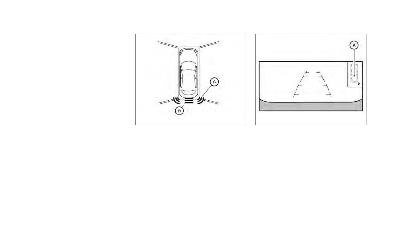
LSD3246
LSD2137
When the corner of the vehicle moves
A will appear when
closer to an object, the corner sonar indi-
the vehicle moves closer to an object.
A appears. When the center of the
vehicle moves close to an object, the cen-
B appears.
Starting and driving
5-125

The system is automatically activated
when the ignition is in the ON position and
the shift lever is in the R (Reverse) position.
Perform the following steps to enable or
disable the sonar system:
For vehicles with the vehicle information
display (if so equipped):
1.
Press the
button until “Settings” dis-
plays in the vehicle information display.
Use the
button to select “Driver As-
sistance.” Then press the OK button.
2.
Select “Parking Aids” and press the OK
button.
3.
Select “Sonar” and press the OK button.
• Select “Rear Sensor” and press the OK
button to turn the sonar system on or
off.
• Select “Display” to display the parking
sensor in the vehicle information dis-
play when the sonar system activates.
• Select “Range” to change the sonar
system distance to “Far,” “Mid” or “Near.”
• Select “Volume” to change the volume
LSD4001
to “High,” “Med,” or “Low.”
HOW TO ENABLE/DISABLE THE
SONAR SYSTEM
5-126
Starting and driving

For vehicles with the RSS OFF switch (if
so equipped):
1. The RSS is automatically enabled when
the ignition switch is placed in the ON
position and the shift lever is in R
(Reverse).
2. Push the RSS OFF switch once to disable
the RSS. The indicator light on the RSS
switch will not illuminate.
The RSS will automatically be turned on
when the engine is restarted.
SONAR LIMITATIONS
WARNING
Listed below are the system limitations
for the sonar system. Failure to operate
the vehicle in accordance with these
system limitations could result in seri-
ous injury or death.
• Read and understand the limitations
of the sonar system as contained in
this section. Inclement weather may
affect the function of the sonar sys-
LSD4002
tem; this may include reduced per-
formance or a false activation.
• The system is deactivated at speeds
above 6 mph (10 km/h). It is reacti-
vated at lower speeds.
Starting and driving
5-127

•
Inclement weather or ultrasonic
SYSTEM TEMPORARILY
sources such as an automatic car
UNAVAILABLE
wash, a truck’s compressed-air
When sonar blockage is detected, the sys-
brakes or a pneumatic drill may af-
tem will be deactivated automatically.
fect the function of the system; this
may include reduced performance or
The system is not available until the condi-
tions no longer exist.
a false activation.
•
The system is not designed to pre-
The sonar sensors may be blocked by tem-
vent contact with small or moving
porary ambient conditions such as splash-
objects. Always move slowly. The
ing water, mist or fog. The blocked condi-
system will not detect small objects
tion may also be caused by objects such as
below the bumper or on the ground.
ice, frost or dirt obstructing the sonar
sensors.
•
The system may not detect the fol-
lowing objects: fluffy objects such as
Action to take:
LSD3516
snow, cloth, cotton, glass-wool, etc.;
When the above conditions no longer exist,
thin objects such as rope, wire and
SYSTEM MAINTENANCE
the system will resume automatically.
chain, etc.; or wedge-shaped objects.
1
are located on the
•
The system may not detect objects
rear bumper. Always keep the area near
at speeds above 3 mph (5 km/h) and
the sonar sensors clean.
may not detect certain angular or
The sonar sensors may be blocked by tem-
moving objects.
porary ambient conditions such as splash-
•
Do not attach stickers
(including
ing water, mist or fog.
transparent material), install acces-
sories, or apply anything blocking
The blocked condition may also be caused
the sensors. These conditions may
by objects such as ice, frost or dirt ob-
reduce the ability of the system.
structing the sonar sensors.
Check for and remove objects obstructing
the area around the sonar sensors.
5-128
Starting and driving