Nissan Versa (2022 year). Manual in english - page 14

MANUAL TRANSMISSION (if so
•
When the vehicle is stopped with the
equipped)
engine running (for example, at a
stop light), shift to N (Neutral) and re-
WARNING
lease the clutch pedal with the foot
brake applied.
•
Do not downshift abruptly on slip-
pery roads. This may cause a loss of
control.
•
Do not over-rev the engine when
shifting to a lower gear. This may
cause a loss of control or engine
damage.
•
Do not shift to the N (Neutral) posi-
tion while driving. Doing so may re-
SSD0535
sult in an accident due to loss of en-
gine braking.
Shifting
To change gears, or when upshifting or
CAUTION
downshifting, depress the
clutch pedal
•
Do not rest your foot on the clutch
fully, shift into the appropriate gear, then
pedal while driving. This may cause
release the clutch slowly and smoothly.
clutch damage.
To ensure smooth gear changes, fully de-
•
Fully depress the clutch pedal before
press the clutch pedal before operating the
shifting to help prevent transmission
shift lever. If the clutch pedal is not fully
damage.
depressed before the transmission is
•
Stop your vehicle completely before
shifted, a gear noise may be heard. Trans-
shifting into R (Reverse).
mission damage could occur.
5-24
Starting and driving
Start the vehicle in 1st gear and shift to 2nd,
For normal acceleration in low altitude ar-
Suggested maximum speed in
3rd, 4th and up to 5th gear in sequence
eas (less than 4,000 ft [1219 m]):
each gear
according to vehicle speed.
GEAR CHANGE
mph (km/h)
Downshift to a lower gear if the engine is
On the manual transmission, you cannot
1st to 2nd
9
(14)
not running smoothly, or if you need to
shift directly from 5th gear into R (Reverse).
accelerate.
2nd to 3rd
12
(19)
First shift into N
(Neutral), then into R
3rd to 4th
21
(34)
Do not exceed the maximum suggested
(Reverse).
4th to 5th
28
(45)
speed (shown below) in any gear. For level
The shift lever ring returns to its original
road driving, use the highest gear sug-
5th
—
position when the shift lever is moved to
gested for that speed. Always observe
the N (Neutral) position.
For quick acceleration in low altitude
posted speed limits, and drive according to
areas and high altitude areas (over 4,000 ft
If it is difficult to move the shift lever into R
the road conditions, which will ensure safe
[1219 m]):
(Reverse) or 1st gear, shift into N (Neutral),
operation. Do not over-rev the engine
then release the clutch pedal. Depress the
when shifting to a lower gear as it may
Gear change
mph (km/h)
clutch pedal again and shift into R (Re-
cause engine damage or loss of vehicle
1st to 2nd
15
(24)
verse) or 1st gear.
control.
2nd to 3rd
25
(40)
3rd to 4th
40
(64)
GEAR
mph (km/h)
Suggested up-shift speeds
4th to 5th
45
(72)
1st
28
(46)
The following are suggested vehicle
5th
—
2nd
52
(83)
speeds for shifting into a higher gear.
3rd
76
(122)
These suggestions relate to fuel economy
and vehicle performance. Actual upshift
4th
103
(166)
speeds will vary according to road condi-
5th
—
tions, the weather and individual driving
habits.
Starting and driving
5-25
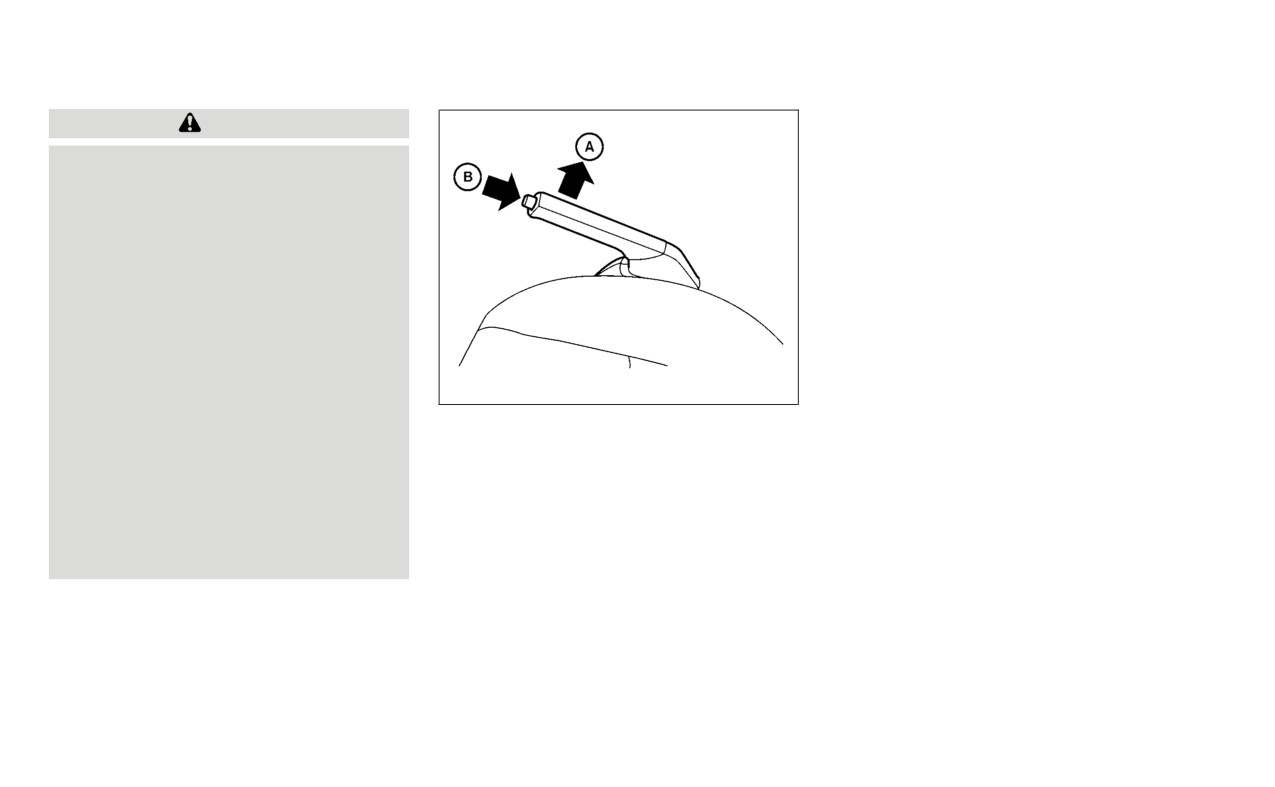
PARKING BRAKE
3.
While pulling up on the parking brake
WARNING
B and
•
Be sure the parking brake is fully re-
lower the lever completely.
leased before driving. Failure to do so
4.
Before driving, be sure
the
brake
can cause brake failure and lead to
warning light goes out.
an accident.
•
Do not release the parking brake
from outside the vehicle.
•
Do not use the shift lever in place of
the parking brake. When parking, be
sure the parking brake is fully
engaged.
•
To help avoid risk of injury or death
through unintended operation of the
WSD0169
vehicle and/or its systems, do not
leave children, people who require
To engage: Pull the parking brake lever up
the assistance of others or pets unat-
A .
tended in your vehicle. Additionally,
To release:
the temperature inside a closed ve-
1. Firmly apply the foot brake.
hicle on a warm day can quickly be-
come high enough to cause a signifi-
2. Manual transmission models:
cant risk of injury or death to people
Place the shift lever in the N (Neutral)
and pets.
position.
Continuously Variable Transmission
models:
Move the shift lever to the P (Park)
position.
5-26
Starting and driving

LANE DEPARTURE WARNING (LDW)
The LDW system will operate when the ve-
hicle is driven at speeds of approximately
37 mph (60 km/h) and above, and only
when the lane markings are clearly visible
on the road.
The LDW system monitors the lane mark-
ers on the traveling lane using the camera
A located above the inside mirror.
The LDW system warns the driver that the
vehicle is beginning to leave the driving
lane with an indicator and a steering wheel
vibration. For additional information,
see
“LDW system operation” (P. 5-28).
LSD3498
WARNING
Failure to follow the warnings and in-
structions for proper use of the LDW
system could result in serious injury or
death.
• This system is only a warning device
to inform the driver of a potential un-
intended lane departure. It will not
steer the vehicle or prevent loss of
control. It is the driver’s responsibility
to stay alert, drive safely, keep the
vehicle in the traveling lane, and be in
control of the vehicle at all times.
Starting and driving
5-27

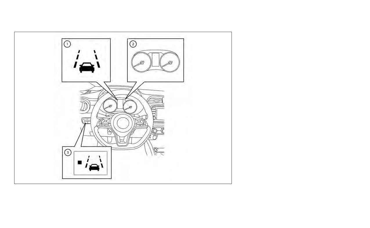
1
Lane Departure Warning (LDW) indica-
tor or Lane Departure Warning (LDW)
indicator light
2
Vehicle Information Display or Trip
Computer
3
LDW Switch (if so equipped)
The LDW system provides a lane departure
warning function when the vehicle is driven
at speeds of approximately 37 mph (60
km/h) and above and the lane markings
are clear. When the vehicle approaches ei-
ther the left or the right side of the traveling
lane, the steering wheel will vibrate and the
LDW indicator (if so equipped) on the in-
strument panel will blink to alert the driver.
The warning function will stop when the
vehicle returns inside of the lane markers.
LSD3988
Vehicle Information Display
LDW SYSTEM OPERATION
5-28
Starting and driving
LSD3989
Trip Computer
Starting and driving
5-29

Perform the following steps to enable or
disable the LDW system.
For vehicles with the vehicle information
display (if so equipped):
1. Press the
button until “Settings” dis-
plays in the vehicle information display.
Use the
button to select “Driver As-
sistance.” Then press the OK button.
2. Select “Lane” and press the OK button.
3. Select
“Lane Departure Warning” and
press the OK button to turn the system
on or off.
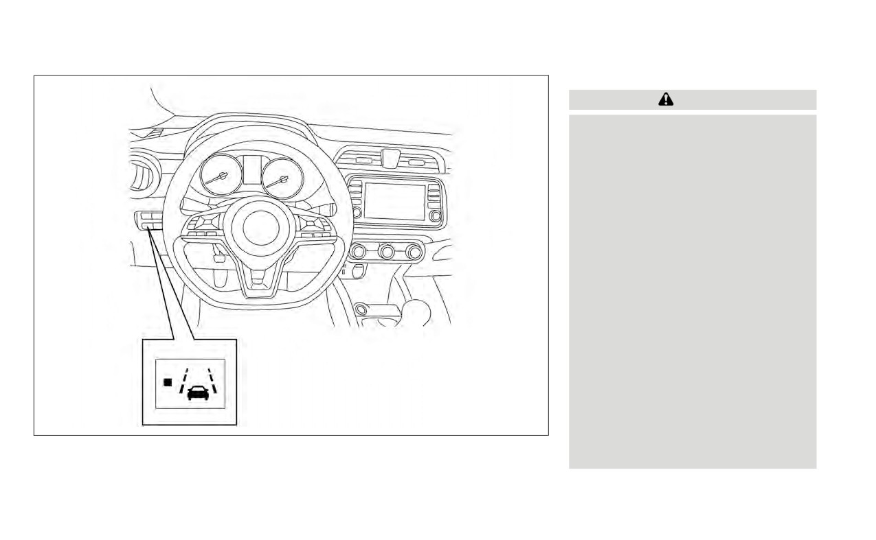
For vehicles with the LDW switch (if so
equipped):
1. Push the Lane Departure Warning (LDW)
switch to turn the LDW system on.
2. Push the LDW switch again to turn the
LDW system off.
When the LDW system is turned on, the
indicator light on the LDW switch
illuminates.
LSD4122
HOW TO ENABLE/DISABLE THE
LDW SYSTEM
5-30
Starting and driving
LDW SYSTEM LIMITATIONS
WARNING
Listed below are the system limitations
for the LDW system. Failure to follow
the warnings and instructions for
proper use of the LDW system could re-
sult in serious injury or death.
•
The system will not operate at
speeds below approximately 37 mph
(60 km/h) or if it cannot detect lane
markers.
•
Do not use the LDW system under the
following conditions as it may not
function properly:
- During bad weather
(rain, fog,
snow, etc.).
- When driving on slippery roads,
such as on ice or snow.
- When driving on winding or un-
even roads.
- When there is a lane closure due to
road repairs.
- When driving in a makeshift or
LSD3991
temporary lane.
- When driving on roads where the
lane width is too narrow.
Starting and driving
5-31
- When driving without normal tire
-
On roads where the traveling lane
SYSTEM TEMPORARILY
conditions (for example, tire wear,
merges or separates.
UNAVAILABLE
low tire pressure, installation of
-
When the vehicle’s traveling direc-
If the vehicle is parked in direct sunlight
spare tire, tire chains, nonstan-
tion does not align with the lane
under high temperature conditions (over
dard wheels).
marker.
approximately
104°F
[40°C]) and then
- When the vehicle is equipped with
-
When traveling close to the ve-
started, the LDW system may be deacti-
non-original brake parts or sus-
hicle in front of you, which ob-
vated automatically and the following
pension parts.
structs the lane camera unit de-
message will appear in the vehicle infor-
- When you are towing a trailer or
tection range.
mation display (if so equipped): “Unavail-
other vehicle.
able: High Cabin Temperature.”
-
When rain, snow, dirt or an object
•
The system may not function prop-
adheres to the windshield in front
When the interior temperature is reduced,
erly under the following conditions:
of the lane camera unit.
the LDW system will resume operating
-
On roads where there are multiple
-
When the headlights are not
automatically.
parallel lane markers; lane mark-
bright due to dirt on the lens or if
The LDW system is not designed to warn
ers that are faded or not painted
the aiming is not adjusted
under the following conditions:
clearly; yellow painted lane mark-
properly.
• When you operate the lane change signal
ers; non-standard lane markers;
-
When strong light enters the lane
and change traveling lanes in the direc-
or lane markers covered with wa-
camera unit. (For example, the
tion of the signal. (The LDW system will
ter, dirt, snow, etc.
light directly shines on the front of
become operable again approximately 2
-
On roads where the discontinued
the vehicle at sunrise or sunset.)
seconds after the lane change signal is
lane markers are still detectable.
-
When a sudden change in bright-
turned off.)
-
On roads where there are sharp
ness occurs. (For example, when
• When the vehicle speed lowers to less
curves.
the vehicle enters or exits a tunnel
than approximately 37 mph (60 km/h).
-
On roads where there are sharply
or under a bridge.)
After the above conditions have finished
contrasting objects, such as shad-
and the necessary operating conditions
ows, snow, water, wheel ruts, seams
are satisfied, the LDW functions will resume.
or lines remaining after road re-
pairs. (The LDW system could detect
these items as lane markers.)
5-32
Starting and driving

SYSTEM MALFUNCTION
•
Do not place reflective materials, such as
white paper or a mirror, on the instru-
If the LDW system malfunctions, it will can-
ment panel. The reflection of sunlight
cel automatically. The LDW indicator (or-
may adversely affect the camera unit’s
ange) or LDW indicator light will illuminate
capability of detecting the lane markers.
in the instrument panel. If the LDW indicator
•
Do not strike or damage the areas
(orange) or LDW indicator light illuminates
around the camera unit. Do not touch the
in the instrument panel, pull off the road to
camera lens or remove the screw located
a safe location and stop the vehicle. Turn
on the camera unit. If the camera unit is
the engine/motor off and restart the
damaged due to an accident, it is recom-
engine/motor. If the LDW indicator (orange)
mended that you visit a NISSAN dealer.
or LDW indicator light continues to illumi-
nate, have the LDW system checked. It is
recommended that you visit a NISSAN
dealer for this service.
LSD3502
SYSTEM MAINTENANCE
A for the LDW sys-
tem is located above the inside mirror. To
keep the proper operation of the LDW sys-
tem and prevent a system malfunction, be
sure to observe the following:
• Always keep the windshield clean.
• Do not attach a sticker (including trans-
parent material) or install an accessory
near the camera unit.
Starting and driving
5-33
BLIND SPOT WARNING (BSW) (if so
equipped)
The BSW system helps alert the driver of
other vehicles in adjacent lanes when
changing lanes.
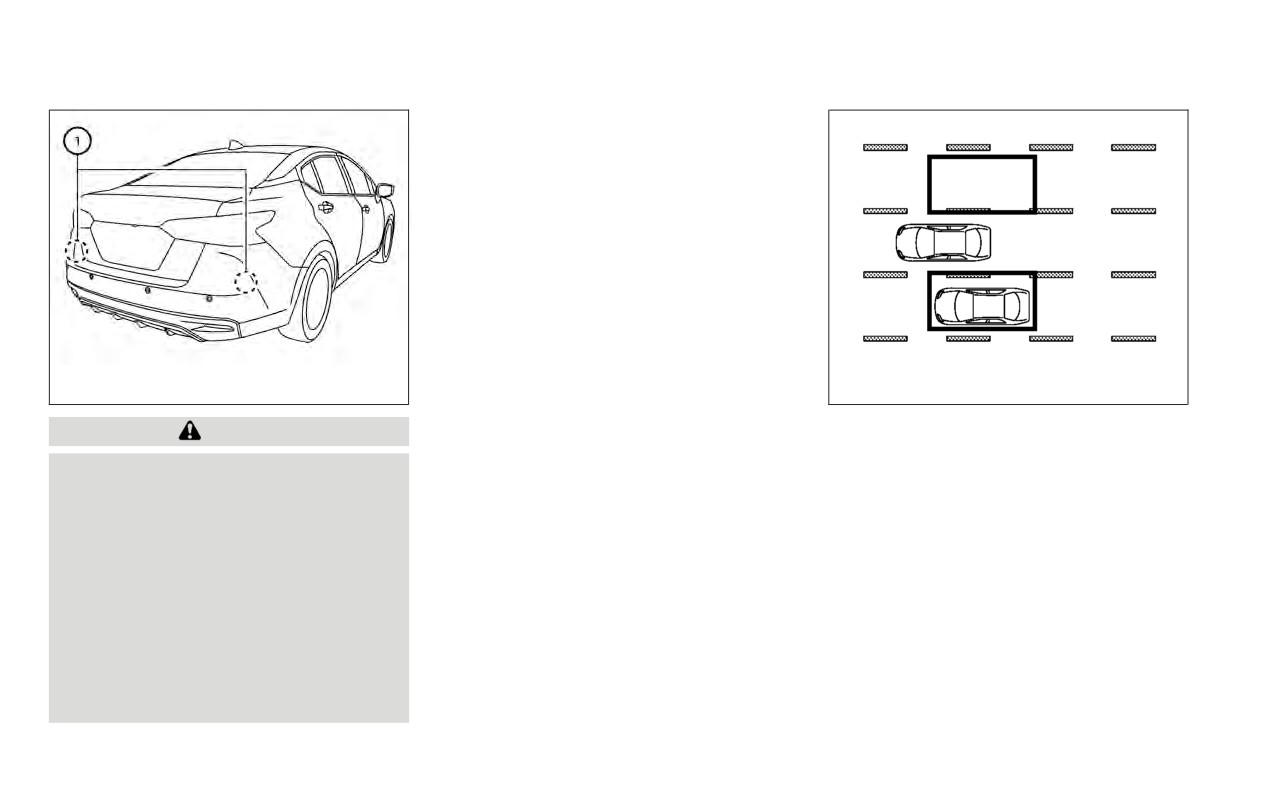
1
installed near the rear bumper to detect
other vehicles in an adjacent lane.
LSD3503
SSD1030
Detection zone
WARNING
The radar sensors can detect vehicles on
Failure to follow the warnings and in-
either side of your vehicle within the detec-
tion zone shown as illustrated. This detec-
structions for proper use of the BSW
system could result in serious injury or
tion zone starts from the outside mirror of
your vehicle and extends approximately 10
death.
ft (3.0 m) behind the rear bumper, and ap-
• The BSW system is not a replacement
proximately 10 ft (3.0 m) sideways.
for proper driving procedures and is
not designed to prevent contact with
vehicles or objects. When changing
lanes, always use the side and rear
mirrors and turn and look in the di-
rection your vehicle will move to en-
sure it is safe to change lanes. Never
rely solely on the BSW system.
5-34
Starting and driving

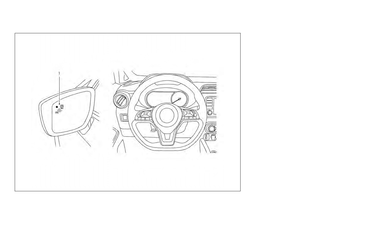
If the radar sensors detect a vehicle in the
detection zone, the side BSW/RCTA indica-
tor light (1) illuminates. If the turn signal is
then activated, the system chimes (twice),
the side BSW/RCTA indicator light flashes
and the BSW indicator illuminates (yellow)
in the vehicle information display. The side
BSW/RCTA indicator light continues to
flash until the detected vehicle leaves the
detection zone.
The side BSW/RCTA indicator light illumi-
nates for a few seconds when the ignition
switch is placed in the ON position.
The brightness of the side BSW/RCTA indi-
cator light is adjusted automatically de-
pending on the brightness of the ambient
light.
If a vehicle comes into the detection zone
after the driver activates the turn signal,
then only the side BSW/RCTA indicator light
flashes and no chime sounds. For addi-
tional information, see “BSW driving situa-
tions” (P. 5-38).
The BSW system automatically turns on
every time the engine is started, as long as
LSD3541
it is activated using the settings menu on
1.
Side BSW/RCTA Indicator Light
BSW SYSTEM OPERATION
the vehicle information display.
2.
BSW indicator
The BSW system operates above approxi-
mately 20 mph (32 km/h).
Starting and driving
5-35

Perform the following steps to enable or
disable the BSW system.
1. Press the
button until “Settings” dis-
plays in the vehicle information display.
Use the
button to select “Driver As-
sistance.” Then press the OK button.
2. Select
“Blind Spot” and press the OK
button.
3. Select “Blind Spot Warning” and press
the OK button to turn the system on or
off.
NOTE:
• When enabling/disabling the system,
the system will retain current settings
even if the engine is restarted.
• When the BSW system is turned on, the
BSW indicator (white) in the vehicle in-
formation display illuminates.
LSD3507
HOW TO ENABLE/DISABLE THE
BSW SYSTEM
5-36
Starting and driving
BSW SYSTEM LIMITATIONS
- A vehicle that passes through the
•
Do not attach stickers
(including
WARNING
detection zone quickly.
transparent material), install acces-
- When overtaking several vehicles
sories or apply additional paint near
Listed below are the system limitations
in a row, the vehicles after the first
the radar sensors. These conditions
for the BSW system. Failure to operate
may reduce the ability of the radar to
vehicle may not be detected if
the vehicle in accordance with these
they are traveling close together.
detect other vehicles.
system limitations could result in seri-
•
The radar sensors’ detection zone is
•
Excessive noise (for example, audio
ous injury or death.
system volume, open vehicle win-
designed based on a standard lane
•
The BSW system cannot detect all ve-
dow) will interfere with the chime
width. When driving in a wider lane,
hicles under all conditions.
the radar sensors may not detect ve-
sound, and it may not be heard.
•
The radar sensors may not be able to
hicles in an adjacent lane. When driv-
detect and activate BSW when cer-
ing in a narrow lane, the radar sen-
tain objects are present such as:
sors may detect vehicles driving two
-
Pedestrian, bicycles, animals.
lanes away.
–
Vehicles such as motorcycles, low
•
The radar sensors are designed to ig-
height vehicles, or high ground
nore most stationary objects; how-
clearance vehicles.
ever, objects such as guardrails,
walls, foliage and parked vehicles
-
Oncoming vehicles.
may occasionally be detected. This is
–
Vehicles remaining in the detec-
a normal operation condition.
tion zone when you accelerate
•
The following conditions may reduce
from a stop.
the ability of the radar to detect other
-
A vehicle merging into an adjacent
vehicles:
lane at a speed approximately the
- Severe weather
same as your vehicle.
- Road spray
-
A vehicle approaching rapidly
from behind.
- Ice/frost/snow/dirt build-up on
the vehicle
-
A vehicle which your vehicle over-
takes rapidly.
Starting and driving
5-37
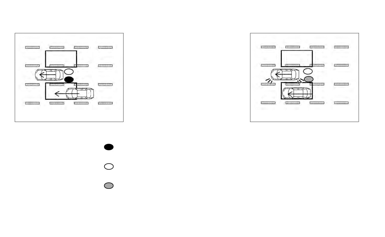
Another vehicle approaching
from behind
Illustration 1: The side BSW/RCTA indicator
light illuminates if a vehicle enters the de-
tection zone from behind in an adjacent
lane.
NOTE:
• The radar sensors may not detect ve-
hicles which are approaching rapidly
from behind.
LSD2299
LSD2300
Illustration 1 - Approaching from behind
Illustration 2 - Approaching from
behind
BSW DRIVING SITUATIONS
Illustration 2: If the driver activates the turn
Indicator on
signal when another vehicle is in the detec-
tion zone, then the system chimes (twice) and
the side BSW/RCTA indicator light flashes.
Indicator off
NOTE:
• The radar sensors may not detect ve-
hicles which are approaching rapidly
Indicator flashing
from behind.
• If the driver activates the turn signal
before a vehicle enters the detection
zone, the side BSW/RCTA indicator
light will flash but no chime will sound
when the other vehicle is detected.
5-38
Starting and driving

• The radar sensors may not detect
slower moving vehicles if they are
passed quickly.
• If the driver activates the turn signal
before a vehicle enters the detection
zone, the side BSW/RCTA indicator
light will flash but no chime will sound
when the other vehicle is detected.
LSD2302
LSD2303
Illustration 3 - Overtaking another
Illustration 4 - Overtaking another
vehicle
vehicle
Overtaking another vehicle
Illustration 4: If the driver activates the
turn signal while another vehicle is in the
Illustration 3: The side BSW/RCTA indica-
detection zone, then the system chimes
tor light illuminates if you overtake a ve-
(twice) and the side BSW/RCTA indicator
hicle and that vehicle stays in the detection
light flashes.
zone for approximately 2 seconds.
NOTE:
• When overtaking several vehicles in a
row, the vehicles after the first vehicle
may not be detected if they are travel-
ing close together.
Starting and driving
5-39

• The radar sensors may not detect a ve-
hicle which is traveling at about the
same speed as your vehicle when it en-
ters the detection zone.
LSD2305
LSD2308
Illustration 5 - Entering from the side
Illustration 6 - Entering from the side
Entering from the side
Illustration 6: If the driver activates the
turn signal while another vehicle is in the
Illustration 5: The side BSW/RCTA indicator
detection zone, then the system chimes
light illuminates if a vehicle enters the de-
(twice) and the side BSW/RCTA indicator
tection zone from either side.
light flashes.
NOTE:
• If the driver activates the turn signal
before a vehicle enters the detection
zone, the side BSW/RCTA indicator
light will flash but no chime will sound
when the other vehicle is detected.
5-40
Starting and driving
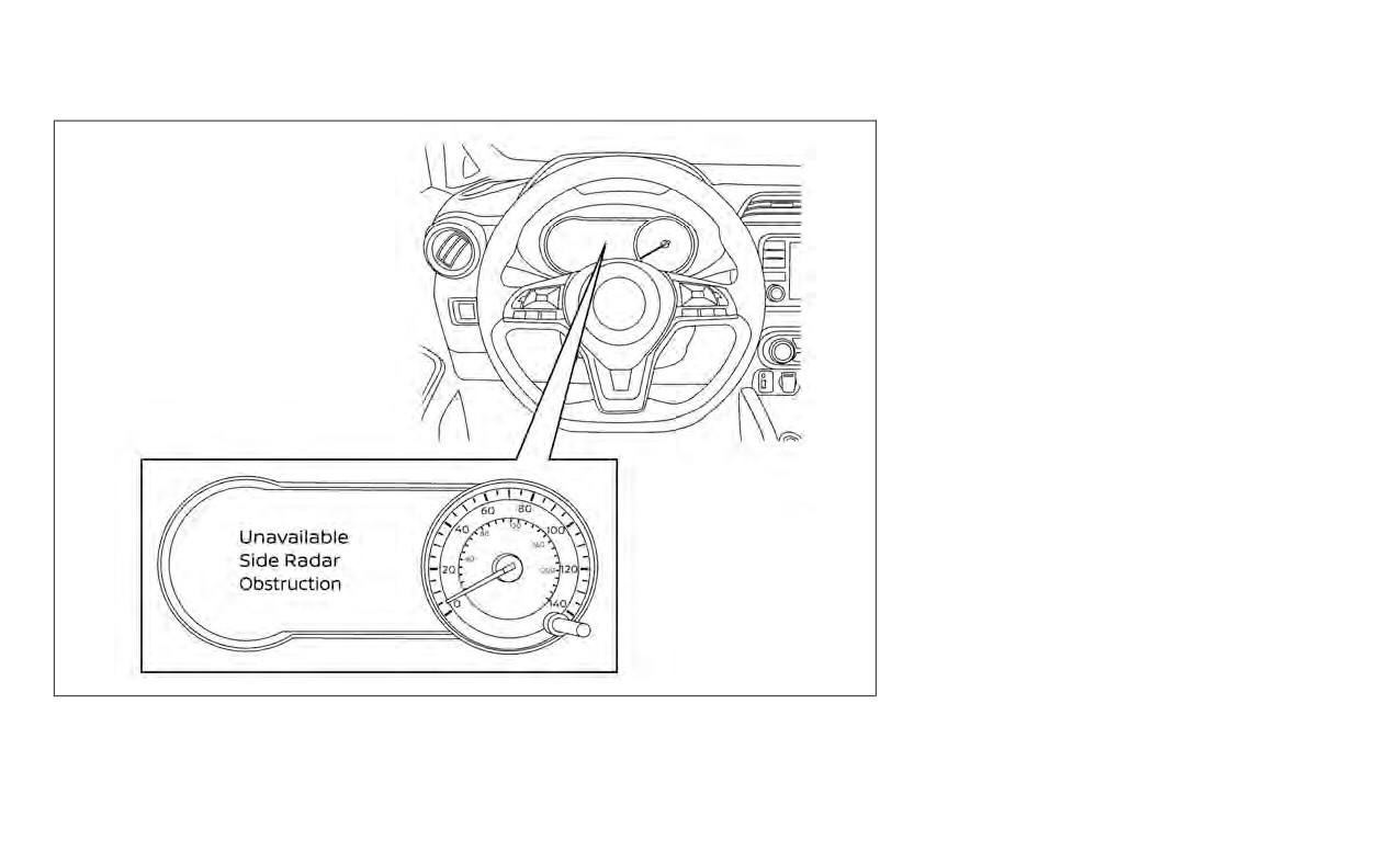
When radar blockage is detected, the sys-
tem will be deactivated automatically. The
“Unavailable: Side Radar Obstruction”
warning message will appear in the vehicle
information display.
The system is not available until the condi-
tions no longer exist.
The radar sensors may be blocked by tem-
porary ambient conditions such as splash-
ing water, mist or fog. The blocked condi-
tion may also be caused by objects such as
ice, frost or dirt obstructing the radar
sensors.
Action to take:
When the above conditions no longer exist,
the system will resume automatically.
NOTE:
If the BSW system stops working, the
RCTA system (if so equipped) will also
stop working.
LSD3566
SYSTEM TEMPORARILY
UNAVAILABLE
Starting and driving
5-41
Malfunction
Do not attach stickers (including transpar-
ent material), install accessories or apply
If the BSW system malfunctions, it will turn
additional paint near the radar sensors.
off automatically. The system malfunction
warning message with the BSW indicator
Do not strike or damage the area around
(orange) will appear in the vehicle informa-
the radar sensors. It is recommended that
tion display.
you visit a NISSAN dealer if the area around
the radar sensors is damaged due to a
NOTE:
collision.
If the BSW system stops working, the
RCTA system (if so equipped) will also
Radio frequency statement
stop working.
For USA
Action to take:
FCC ID: OAYSRR2B or OAYSRR3B
Stop the vehicle in a safe location, place the
This device complies with part 15 of the
LSD3503
vehicle in the P (Park) position, turn the en-
FCC Rules. Operation is subject to the fol-
gine off and restart the engine. If the mes-
SYSTEM MAINTENANCE
lowing two conditions:
sage continues to appear, have the system
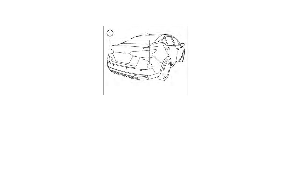
1
for the BSW and
(1) This device may not cause harmful
checked. It is recommended that you visit a
RCTA systems are located near the rear
interference, and (2) this device must ac-
NISSAN dealer for this service.
bumper. Always keep the area near the ra-
cept any interference received, including
dar sensors clean.
interference that may cause undesired
operation.
The radar sensors may be blocked by tem-
porary ambient conditions such as splash-
FCC Warning
ing water, mist or fog.
Changes or modifications not expressly
The blocked condition may also be caused
approved by the party responsible for
by objects such as ice, frost or dirt ob-
compliance could void the user’s author-
structing the radar sensors.
ity to operate the equipment
Check for and remove objects obstructing
the area around the radar sensors.
5-42
Starting and driving
REAR CROSS TRAFFIC ALERT (RCTA)
(if so equipped)
For Canada
WARNING
Applicable law: Canada 310
Failure to follow the warnings and in-
This device complies with Industry
structions for proper use of the RCTA
Canada licence-exempt RSS standard(s).
system could result in serious injury or
Operation is subject to the following two
death.
conditions: (1) this device may not cause
• The RCTA system is not a replace-
interference, and (2) this device must ac-
ment for proper driving procedures
cept any interference, including interfer-
and is not designed to prevent con-
ence that may cause undesired opera-
tact with vehicles or objects. When
tion of the device.
backing out of a parking space, al-
Frequency bands: 24.05GHz - 24.25GHz
ways use the side and rear mirrors
and turn and look in the direction
Output power: less than 20 milliwatts
your vehicle will move. Never rely
solely on the RCTA system.
The RCTA system will assist you when
backing out from a parking space. When
the vehicle is in reverse, the system is de-
signed to detect other vehicles approach-
ing from the right or left of the vehicle. If the
system detects cross traffic, it will alert you.
Starting and driving
5-43
The RCTA system can help alert the driver
of an approaching vehicle when the driver
is backing out of a parking space.
When the shift position is in R (Reverse) and
the vehicle speed is less than approxi-
mately 5 mph (8 km/h), the RCTA system is
operational.
If the radar detects an approaching vehicle
from either side, the system chimes (once)
and the side BSW/RCTA indicator light
flashes on the side the vehicle is approach-
ing from.
LSD3540
RCTA SYSTEM OPERATION
1. Side BSW/RCTA Indicator Light
5-44
Starting and driving