Nissan Murano Z51 (2013 year). Manual - part 84


  Index      Manuals     Nissan Murano Z51 (2013 year) - Service and Repair Manual


Search            copyright infringement  


Content      ..     82      83      84      85     ..


Nissan Murano Z51 (2013 year). Manual - part 84


ST-52

< REMOVAL AND INSTALLATION >

[WITH HEATED STEERING WHEEL]

STEERING GEAR AND LINKAGE

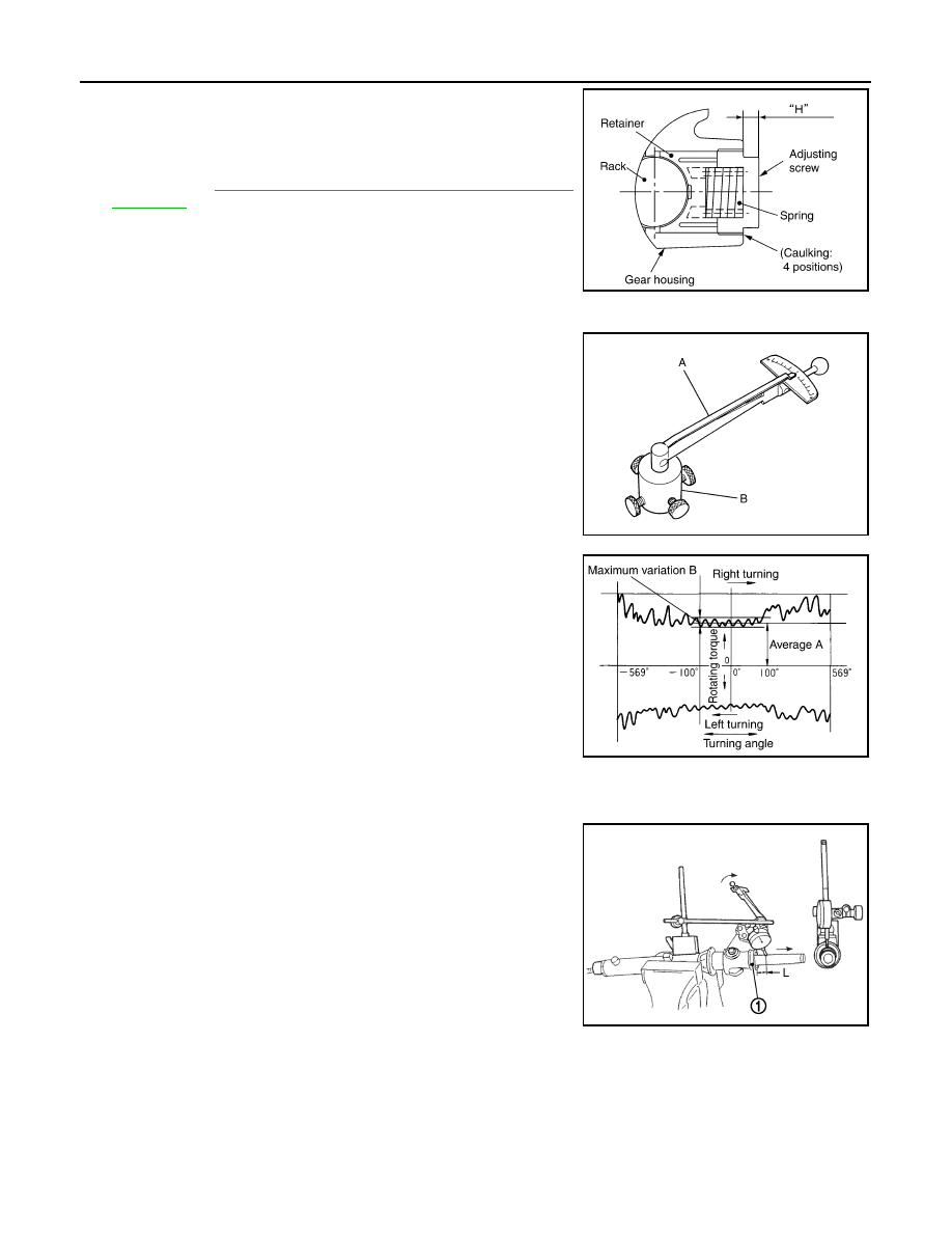
12. Apply recommended thread locking sealant to the thread (2

turns thread), and then screw in the adjusting screw until it
reaches height “H” from gear housing assembly measured
before disassembling.
Use Genuine High Performance Thread Sealant or equiva-
lent. Refer to 

GI-22, "Recommended Chemical Products and

Sealants"

.

13. Move rack assembly 10 strokes throughout the full stroke so that

the parts can fit with each other.

14. Adjust pinion rotating torque with the following procedure.
a.

Measure pinion rotating torque within 

±

180

°

 of neutral position

of the rack assembly using Tools. Stop the gear at the point
where highest torque is read.

b.

Loosen adjusting screw and retighten to 5.4 N·m (0.55 kg-m, 48
in-lb), and then loosen by 20 to 40

°

.

c.

Measure pinion rotating torque using Tools to make sure that the
measured value is within the standard. Readjust if the value is
outside the standard. Replace steering gear assembly, if the
value is outside the standard after readjusting, or adjusting
screw rotating torque is 5 N·m (0.51 kg-m, 44 in-lb) or less.

d.

Apply recommended liquid gasket to inner socket and turn pinion fully to left with inner socket installed to
gear housing assembly.

e.

Install dial gauge at 5 mm (0.20 in) (L) from the edge of gear
housing assembly (1), and tooth point.

f.

Measure vertical movement of rack assembly when pinion is
turned clockwise with torque of 19.6 N·m (2.0 kg-m, 14 ft-lb).
Readjust adjusting screw angle if the measured value is outside
the standard.

• If reading is outside of the specification, readjust screw angle

with adjusting screw.

CAUTION:

• If reading is still outside of specification, or if the rotating torque of adjusting screw is less

than 5 N·m (0.51 kg-m, 44 in-lb), replace steering gear assembly.

• Never turn adjusting screw more than twice.
• Replace steering gear assembly when adjusting screw is removed or turned more than twice.

SGIA0624E

A: Preload gauge [SST: ST3127S000 (J-25765-A)]

B: Preload adapter [SST: KV48103400 (

)]

SGIA1383E

Pinion rotating torque

Around neutral position 
(within

±

100

°

) average (A)

: 1.59 – 2.0 N·m (0.17 – 
0.20 kg-m, 14 – 17 in-lb)

Maximum variation (B)

: 0.39 N·m (0.04 kg-m, 3.0 
in-lb)

Vertical movement

: 0.265 mm (0.0104 in)

SGIA0936E

JSGIA0104ZZ

Revision: 2012 September

2013 MURANO

STEERING GEAR AND LINKAGE

ST-53

< REMOVAL AND INSTALLATION >

[WITH HEATED STEERING WHEEL]

C

D

E

F

H

I

J

K

L

M

A

B

ST

N

O

P

15. Install large end of boot to gear housing assembly.

16. Install small end of boot to inner socket boot mounting groove.
17. Install boot clamp to boot small end.

18. Install boot clamp to the large side of boot with the following procedure.

CAUTION:

Never reuse boot clamp.

a.

Tighten large side of boot with boot clamp (stainless wire).

b.

Wrap clamp around boot groove for two turns. Insert a flat-
bladed screwdriver in loops on both ends of wire. Twist 4 to 4.5
turns while pulling them with force of approximately 98 N (10 kg,
22 lb).

c.

Twist boot clamp as shown. Pay attention to relationship
between winding and twisting directions.

d.

Twisted area (A) of clamp is in the opposite side of adjusting
screw (1) as shown in the figure (to prevent contact with other
parts).

SGIA1325E

Wire length (L)

: 370 mm (14.57 in)

SGIA0163E

SGIA0164E

JSGIA0324ZZ

Revision: 2012 September

2013 MURANO

ST-54

< REMOVAL AND INSTALLATION >

[WITH HEATED STEERING WHEEL]

STEERING GEAR AND LINKAGE

e.

Bent cut end of the wire toward rack axial as shown in the figure
after twisting the wire 4 to 4.5 turns so that cut end does not con-
tact with boot.

19. Install cylinder tubes to gear housing assembly.

20. Install low pressure piping.

21. Adjust inner socket to standard length (L), and then tighten lock

nut (1) to the specified torque. Check length again after tighten-
ing lock nut.

CAUTION:

Adjust toe-in after this procedure. The length achieved after
toe-in adjustment is not necessary the above value.

Inspection

INFOID:0000000008459303

INSPECTION AFTER DISASSEMBLY

Boot

Check boot for cracks, and replace it if a malfunction is detected.

Rack Assembly

Check rack for damage or wear, and replace it if a malfunction is detected.

Gear-Sub Assembly

• Check gear-sub assembly for damage or wear, and replace it if a malfunction is detected.
• Rotate gear-sub assembly and check for torque variation or rattle, and replace it if a malfunction is detected.

Gear Housing Assembly

Check gear housing assembly for damage and scratches (inner wall). Replace if there are.

Outer Socket and Inner Socket

Check the following items and replace the component if it does not meet the standard.

BALL JOINT SWINGING TORQUE

Hook a spring balance at the point shown in the figure and pull the
spring balance. Make sure that the spring balance reads the speci-
fied value when ball stud and inner socket start to move. Replace
outer socket and inner socket if they are outside the standard.

A

: Gear housing RHD side

B

: Gear housing LHD side

JSGIA0325ZZ

Standard

Inner socket length (L)

: Refer to 

ST-66, "Inner 

Socket Length"

.

JPGIA0187ZZ

Standard

(Measuring point of outer socket: Stud cotter pin 
mounting hole)

Outer socket

: Refer to 

ST-66, "Socket 

Swing Force and Rotating 
Torque"

.

SGIA0896E

Revision: 2012 September

2013 MURANO

STEERING GEAR AND LINKAGE

ST-55

< REMOVAL AND INSTALLATION >

[WITH HEATED STEERING WHEEL]

C

D

E

F

H

I

J

K

L

M

A

B

ST

N

O

P

BALL JOINT ROTATING TORQUE

Make sure that the reading is within the following specified range
using preload gauge (A) [SST: ST3127S000 (J-25765-A)]. Replace
outer socket if the reading is outside the specified value.

BALL JOINT AXIAL END PLAY

Apply an axial load of 490 N (50 kg, 110 lb) to ball stud. Using a dial
gauge, measure amount of stud movement, and then make sure that
the value is within the following specified range. Replace outer
socket (1) and inner socket (2) if the measured value is outside the
standard.

INSPECTION AFTER INSTALLATION

• Check if steering wheel turns smoothly when it is turned several times fully to the end of the left and right.
• Check the steering wheel play, neutral position steering wheel, steering wheel turning force, and front wheel

turning angle. Refer to 

ST-33, "Inspection"

.

• Check the fluid level, fluid leakage, and air bleeding hydraulic system. Refer to 

ST-31, "Inspection"

.

Standard 

(Measuring point of inner socket: “*” mark shown in 
the figure)

Inner socket

Refer to 

ST-66, "Socket 

Swing Force and Rotating 
Torque"

.

Standard

Rotating torque

: Refer to 

ST-66, "Socket 

Swing Force and Rotating 
Torque"

.

SGIA1382E

Standard

Outer socket

Refer to 

ST-66, "Socket Axial 

End Play"

.

Inner socket

: Refer to 

ST-66, "Socket Axial 

End Play"

.

JSGIA0109ZZ

Revision: 2012 September

2013 MURANO

ST-56

< REMOVAL AND INSTALLATION >

[WITH HEATED STEERING WHEEL]

POWER STEERING OIL PUMP

POWER STEERING OIL PUMP

Exploded View

INFOID:0000000008459304

REMOVAL

DISASSEMBLY

1.

Power steering oil pump

: Vehicle front

Refer to 

GI-4, "Components"

 for symbols in the figure.

JSGIA0326GB

1.

Pulley

2.

Oil seal

3.

Front bracket

4.

Suction pipe

5.

O-ring 

6.

Body assembly 

7.

Flow control valve spring

8.

Flow control valve 

9.

Flow control valve sub assembly

JSGIA0327GB

Revision: 2012 September

2013 MURANO

POWER STEERING OIL PUMP

ST-57

< REMOVAL AND INSTALLATION >

[WITH HEATED STEERING WHEEL]

C

D

E

F

H

I

J

K

L

M

A

B

ST

N

O

P

Removal and Installation

INFOID:0000000008459305

REMOVAL

1.

Drain power steering fluid from reservoir tank.

2.

Remove front road wheel and tires.

3.

Remove splash guard. Refer to 

EXT-23, "FENDER PROTECTOR : Exploded View"

.

4.

Loosen drive belt. Refer to 

EM-16, "Removal and Installation"

.

5.

Remove drive belt from oil pump pulley.

6.

Remove copper washers and eye bolt (drain fluid from their pipings).

7.

Remove suction hose (drain fluid from their pipings).

8.

Remove oil pump mounting bolts, and then remove oil pump.

CAUTION:

Never damage drive shaft boot.

INSTALLATION

Note the following, and install in the reverse order of removal.
• When installing suction hoses (1), refer to the figure.

CAUTION:

• Never apply fluid to the hose (1) and tube (2).
• Insert hose securely until it contacts spool (A) of tube.
• Leave clearance (L) when installing clamp (3).

• When installing eye bolt (1) and copper washers (2) to oil pump

(3), refer to the figure.

CAUTION:

• Never reuse copper washer.
• Apply power steering fluid to around copper washer, then

install eye bolt.

• Install eye bolt with eye joint (assembled to high pressure

hose) (B) protrusion (A) facing with pump side cutout, and
then tighten it to the specified torque after tightening by
hand. Refer to 

ST-62, "Exploded View"

.

• Securely insert harness connector to pressure sensor.

• Adjust belt tension. Refer to 

EM-16, "Tension Adjustment"

.

• Check fluid level, fluid leakage and air bleeding hydraulic system after the installation. Refer to 

ST-31,

"Inspection"

.

Disassembly and Assembly

INFOID:0000000008459306

DISASSEMBLY

1.

Remove rear bracket.

10. O-ring

11.

O-ring

12. Front side plate

13. Vane

14. Rotor

15. Cam ring 

16. Dowel pin

17. Rear side plate

18. O-ring

19. Teflon ring

20. Rear cover

21. Rear bracket

A.

Oil seal lip

: Apply power steering fluid.

: Apply multi-purpose grease.

Refer to 

GI-4, "Components"

 for symbols not described on the above.

Standard

L

: 3 – 8 mm (0.12 – 0.31 in)

JSGIA0118ZZ

SGIA1379E

Revision: 2012 September

2013 MURANO

ST-58

< REMOVAL AND INSTALLATION >

[WITH HEATED STEERING WHEEL]

POWER STEERING OIL PUMP

2.

Remove rear cover mounting bolts, and then remove rear cover from body assembly.

CAUTION:

• Fix oil pump with a vise if necessary.
• Use copper plates when fixing with a vise.

3.

Remove O-ring from body assembly.

4.

Remove rear side plate from cartridge, and then remove Teflon ring and O-ring from rear side plate.

5.

Remove rotor snap ring (1) using a snap ring pliers, and remove
cam ring, rotor and vane from body assembly.

CAUTION:

When removing the snap ring, never damage the pulley
shaft.

6.

Remove front side plate.

7.

Remove cartridge, flow control valve (1), flow control valve
spring (2) and flow control valve sub assembly (3) from body
assembly (4).

CAUTION:

Never drop and damage flow control valve and flow control
valve sub assembly when removing.

8.

Remove oil seal from body assembly.

9.

Remove mounting bolt of suction pipe, and then remove suction
pipe from body assembly.

10. Remove pulley from body assembly.
11. Remove front bracket from body assembly.

12. Remove oil seal from body assembly using a flat-bladed screw-

driver.

CAUTION:

Never damage the body assembly.

ASSEMBLY

1.

Apply recommended grease to oil seal lips (1). Apply recom-
mended fluid to around oil seal. Install oil seal to body assembly
using a drift (commercial service tool).

CAUTION:

• Never reuse the oil seal.
• Fix oil pump with a vise if necessary.
• Use copper plates when fixing with a vise.

2.

Install front bracket to body assembly.

3.

Install pulley to body assembly.

4.

If dowel pin has been removed, insert it into body assembly by
hand. If it cannot be inserted by hand, lightly tap with a hammer.

JSGIA0328ZZ

JSGIA0329ZZ

JSGIA0331ZZ

JSGIA0330ZZ

Revision: 2012 September

2013 MURANO

POWER STEERING OIL PUMP

ST-59

< REMOVAL AND INSTALLATION >

[WITH HEATED STEERING WHEEL]

C

D

E

F

H

I

J

K

L

M

A

B

ST

N

O

P

5.

Install flow control valve (1), flow control valve spring (2) and
flow control valve sub assembly (3) as shown in the figure to
body assembly (4).

6.

Install front side plate (3) with dowel pin (2) on flow control valve
A (1) side as shown in the figure aligning with front side plate
cutout (A) to body assembly (4).

7.

Install cam ring as shown in the figure.

8.

Install rotor so that mark faces body assembly, and then install it
to pulley shaft.

9.

Install vane to rotor so that arc of vane faces cam ring side.

10. Install rotor snap ring to slit of pulley shaft using a hammer and a

drift (commercial service tool).

CAUTION:

• Never damage rotor and pulley shaft.
• Oil pump assembly must be replaced if rotor is damaged.

JSGIA0329ZZ

SGIA1189E

SGIA0612E

SGIA0989E

SGIA0613E

Revision: 2012 September

2013 MURANO

ST-60

< REMOVAL AND INSTALLATION >

[WITH HEATED STEERING WHEEL]

POWER STEERING OIL PUMP

11. Install rear side plate with dowel pin A on flow control valve A

side as shown in the figure aligning with rear side plate cutout B
to cartridge.

12. Apply recommended fluid to O-ring, and then install O-ring to

body assembly.

13. Apply recommended fluid to O-ring, and then install O-ring to

rear side plate.

14. Apply recommended fluid to Teflon ring, and then install Teflon

ring to rear side plate.

15. Install rear cover to body assembly.

16. Apply recommended fluid to O-ring, and then install O-ring to

body assembly.

17. Install suction pipe to body assembly.

18. Install rear bracket.

Inspection

INFOID:0000000008459307

RELIEF OIL PRESSURE

CAUTION:

Make sure that belt tension is normal before starting the following procedure.
1.

Connect the oil pressure gauge [SST: KV48103500 (J-26357)]
and the oil pressure gauge adapter [SST: KV48102500 (J-
33914)] between oil pump discharge connector and high-pres-
sure hose. Bleed air from the hydraulic circuit while opening
valve fully. Refer to 

ST-31, "Inspection"

.

2.

Start the engine. Run the engine until oil temperature reaches
50 to 80

°

C (122 to 176

°

F).

CAUTION:

• Leave the valve of the oil pressure gauge fully open while

starting and running the engine. If engine is started with
the valve closed, the hydraulic pressure in oil pump goes
up to the relief pressure along with unusual increase of oil
temperature.

• Be sure to keep hose clear of belts and other parts when

engine is started.

3.

Fully close the oil pressure gauge valve with engine at idle and
measure the relief oil pressure.

CAUTION:

Never keep valve closed for 10 seconds or longer.

4.

Open the valve slowly after measuring. Repair oil pump if the relief oil pressure is outside the standard.
Refer to 

ST-57, "Disassembly and Assembly"

.

5.

Disconnect the oil pressure gauge from hydraulic circuit.

PGIA0035E

Standard

Relief oil pressure

: Refer to 

ST-66, "Relief Oil 

Pressure"

.

SGIA0915E

Revision: 2012 September

2013 MURANO

POWER STEERING OIL PUMP

ST-61

< REMOVAL AND INSTALLATION >

[WITH HEATED STEERING WHEEL]

C

D

E

F

H

I

J

K

L

M

A

B

ST

N

O

P

6.

When installing eye bolt (1) and copper washers (2) to oil pump
(3), refer to the figure.

CAUTION:

• Never reuse copper washer.
• Apply power steering fluid or equivalent to around copper

washer, then install eye bolt.

• Install eye bolt with eye joint (assembled to high pressure

hose) (B) protrusion (A) facing with pump side cutout, and
then tighten it to the specified torque after tightening by
hand. Refer to 

ST-62, "Exploded View"

.

• Securely insert harness connector to pressure sensor.

7.

Check fluid level, fluid leakage and air bleeding hydraulic sys-
tem after the installation. Refer to 

ST-31, "Inspection"

.

BEFORE DISASSEMBLY

Disassemble oil pump only when the following malfunctions occur.
• If oil leakage is found on oil pump.
• Oil pump pulley is damaged or deformed.
• Performance of oil pump is low. 

AFTER DISASSEMBLY

Body Assembly and Rear Cover Inspection

• Check body assembly and rear cover for internal damage. Replace rear cover if it is damaged. Replace oil

pump assembly if body assembly is damaged.

Cartridge Assembly Inspection

• Check cam ring, rotor and vane for damage. Replace cartridge assembly if necessary.

Side Plate Inspection

• Check side plate for damage. Replace side plate if necessary.

Flow Control Valve Inspection

• Check flow control valve and spring for damage. Replace if necessary.

SGIA1379E

Revision: 2012 September

2013 MURANO

ST-62

< REMOVAL AND INSTALLATION >

[WITH HEATED STEERING WHEEL]

HYDRAULIC LINE

HYDRAULIC LINE

Exploded View

INFOID:0000000008459308

Removal and Installation

INFOID:0000000008459309

CAUTION:

1.

Reservoir tank bracket

2.

Bushing

3.

Reservoir tank

4.

Suction hose

5.

Clamp

6.

Copper washer

7.

High pressure piping

8.

Steering gear assembly

9.

Low pressure hose

10. Eye bolt

A.

To power steering oil pump suction 
hose.

B.

To power steering oil pump.

: Vehicle front

: Apply power steering fluid.

Refer to 

GI-4, "Components"

 for symbols not described on the above.

JSGIA0608GB

Revision: 2012 September

2013 MURANO

HYDRAULIC LINE

ST-63

< REMOVAL AND INSTALLATION >

[WITH HEATED STEERING WHEEL]

C

D

E

F

H

I

J

K

L

M

A

B

ST

N

O

P

• Never apply fluid to the hose (1) and tube (2).
• Insert hose securely until it contacts spool (A) of tube.
• Leave clearance (L) when installing clamp (3).

• Install eye bolt with eye joint (assembled to high pressure

hose) (B) protrusion (A) facing with pump side cutout, and
then tighten it to the specified torque after tightening by hand.
Refer to 

ST-62, "Exploded View"

.

• Securely insert harness connector to pressure sensor.
• Apply power steering fluid to around copper washer, then

install eye bolt.

• Never reuse copper washer.

Standard

L

: 3 – 8 mm (0.12 – 0.31 in)

JSGIA0118ZZ

SGIA1379E

Revision: 2012 September

2013 MURANO

ST-64

< REMOVAL AND INSTALLATION >

[WITH HEATED STEERING WHEEL]

HEATED STEERING WHEEL SWITCH

HEATED STEERING WHEEL SWITCH

Removal and Installation

INFOID:0000000008459310

REMOVAL

1.

Remove Instrument lower panel LH. Refer to 

IP-13, "Removal and Installation"

.

2.

Remove heated steering wheel switch.

INSTALLATION

Install in the reverse order of removal.

Revision: 2012 September

2013 MURANO

SERVICE DATA AND SPECIFICATIONS (SDS)

ST-65

< SERVICE DATA AND SPECIFICATIONS (SDS) 

[WITH HEATED STEERING WHEEL]

C

D

E

F

H

I

J

K

L

M

A

B

ST

N

O

P

SERVICE DATA AND SPECIFICATIONS (SDS)

SERVICE DATA AND SPECIFICATIONS (SDS)

General Specifications

INFOID:0000000008459311

Steering Wheel Axial End Play and Play

INFOID:0000000008459312

Unit: mm (in)

Steering Wheel Turning Force

INFOID:0000000008459313

Unit: N·m (kg-m, in-lb)

Steering Angle

INFOID:0000000008459314

Unit: Degree minute (Decimal degree)

Steering Column Length

INFOID:0000000008459315

Unit: mm (in)

Steering Column Mounting Dimensions

INFOID:0000000008459316

Unit: mm (in)

Steering Column Operating Range

INFOID:0000000008459317

Steering gear model

PR26AF

Fluid capacity (Approx.)

 (US qt, lmp qt)

1.0 (1-1/8, 7/8)

Item

Standard

Steering wheel axial end play

0 (0)

Steering wheel play on the outer circumference

0 – 35 (0 – 1.38)

Item

Standard

Steering wheel turning force

7.45 (0.76, 66)

Item

Standard

Wheel size: 18 inch

Wheel size: 20 inch

Inner wheel

Minimum

33

°

30

 (33.5

°

)

32

°

00

 (32.0

°

)

Nominal

36

°

30

 (36.5

°

)

35

°

00

 (35.0

°

)

Maximum

37

°

30

 (37.5

°

)

36

°′

 (36.0

°

)

Outer wheel

Nominal

31

°

30

 (31.5

°

)

30

°

30

 (30.5

°

)

Item

Standard

Steering column length

463 (18.23)

Item

Standard

Mounting dimension

30 (1.18) or less

Item

Standard

Without electric motor

With electric motor

Tilt operating range 

15

°

18

°

Telescopic operating range 

40 mm (1.57 in)

Rotating torque

0.49 N·m (0.05 kg-m, 4 in-lb)

Revision: 2012 September

2013 MURANO

ST-66

< SERVICE DATA AND SPECIFICATIONS (SDS) 

[WITH HEATED STEERING WHEEL]

SERVICE DATA AND SPECIFICATIONS (SDS)

Lower Shaft Length

INFOID:0000000008459318

Unit: mm (in)

Rack Sliding Force

INFOID:0000000008459319

Unit: N (kg, lb)

Rack Stroke

INFOID:0000000008459320

Unit: mm (in)

Socket Swing Force and Rotating Torque

INFOID:0000000008459321

SWING FORCE

Unit: N (kg, lb)

ROTATING TORQUE

Unit: N·m (kg-m, in-lb)

Socket Axial End Play

INFOID:0000000008459322

Unit: mm (in)

Inner Socket Length

INFOID:0000000008459323

Unit: mm (in)

Relief Oil Pressure

INFOID:0000000008459324

Unit: kPa (kg/cm

2

, psi)

Item

Standard

Lower shaft length (extended position)

524.6 – 525.6 (20.65 – 20.69)

Item

Standard

2WD

AWD

Rack sliding force

195 – 258 (19.9 – 26.3, 43.8 – 

57.9)

227 – 305 (23.2 – 31.1, 51.1 – 

68.5)

Item

Standard

Wheel size: 18 inch

Wheel size: 20 inch

Rack stroke neutral position

70.5 (2.776)

68.0 (2.677)

Item

Standard

Outer socket

4.81 – 45.7 (0.5 – 4.6, 1.1 – 10.2)

Inner socket

8.9 – 64 (0.91 – 6.5, 2.01 – 14.3)

Item

Standard

Outer socket 

0.3 – 2.9 (0.03 – 0.29, 3 – 25)

Item

Standard

Outer socket

0.5 (0.02) or less

Inner socket

0.2 (0.008) or less

Item

Standard

Inner socket length

120.6 (4.75)

Item

Standard

Relief oil pressure

9,400 – 10,400 (95.9 – 106.1, 1,363 – 1,508)

Revision: 2012 September

2013 MURANO

PRECAUTIONS

ST-67

< PRECAUTION >

[WITHOUT HEATED STEERING WHEEL]

C

D

E

F

H

I

J

K

L

M

A

B

ST

N

O

P

PRECAUTION

PRECAUTIONS

FOR USA AND CANADA

FOR USA AND CANADA : Precaution for Supplemental Restraint System (SRS) "AIR 
BAG" and "SEAT BELT PRE-TENSIONER"

INFOID:0000000008942354

The Supplemental Restraint System such as “AIR BAG” and “SEAT BELT PRE-TENSIONER”, used along
with a front seat belt, helps to reduce the risk or severity of injury to the driver and front passenger for certain
types of collision. This system includes seat belt switch inputs and dual stage front air bag modules. The SRS
system uses the seat belt switches to determine the front air bag deployment, and may only deploy one front
air bag, depending on the severity of a collision and whether the front occupants are belted or unbelted.
Information necessary to service the system safely is included in the “SRS AIR BAG” and “SEAT BELT” of this
Service Manual.

WARNING:

Always observe the following items for preventing accidental activation.
• To avoid rendering the SRS inoperative, which could increase the risk of personal injury or death in

the event of a collision that would result in air bag inflation, all maintenance must be performed by
an authorized NISSAN/INFINITI dealer.

• Improper maintenance, including incorrect removal and installation of the SRS, can lead to personal

injury caused by unintentional activation of the system. For removal of Spiral Cable and Air Bag
Module, see “SRS AIR BAG”.

• Never use electrical test equipment on any circuit related to the SRS unless instructed to in this Ser-

vice Manual. SRS wiring harnesses can be identified by yellow and/or orange harnesses or harness
connectors.

PRECAUTIONS WHEN USING POWER TOOLS (AIR OR ELECTRIC) AND HAMMERS

WARNING:

Always observe the following items for preventing accidental activation.
• When working near the Air Bag Diagnosis Sensor Unit or other Air Bag System sensors with the

ignition ON or engine running, never use air or electric power tools or strike near the sensor(s) with
a hammer. Heavy vibration could activate the sensor(s) and deploy the air bag(s), possibly causing
serious injury.

• When using air or electric power tools or hammers, always switch the ignition OFF, disconnect the

battery, and wait at least 3 minutes before performing any service.

FOR MEXICO

FOR MEXICO : Precaution for Supplemental Restraint System (SRS) "AIR BAG" and 
"SEAT BELT PRE-TENSIONER"

INFOID:0000000008942355

The Supplemental Restraint System such as “AIR BAG” and “SEAT BELT PRE-TENSIONER”, used along
with a front seat belt, helps to reduce the risk or severity of injury to the driver and front passenger for certain
types of collision. Information necessary to service the system safely is included in the “SRS AIR BAG” and
“SEAT BELT” of this Service Manual.

WARNING:

Always observe the following items for preventing accidental activation.
• To avoid rendering the SRS inoperative, which could increase the risk of personal injury or death in

the event of a collision that would result in air bag inflation, all maintenance must be performed by
an authorized NISSAN/INFINITI dealer.

• Improper maintenance, including incorrect removal and installation of the SRS, can lead to personal

injury caused by unintentional activation of the system. For removal of Spiral Cable and Air Bag
Module, see “SRS AIR BAG”.

• Never use electrical test equipment on any circuit related to the SRS unless instructed to in this Ser-

vice Manual. SRS wiring harnesses can be identified by yellow and/or orange harnesses or harness
connectors.

PRECAUTIONS WHEN USING POWER TOOLS (AIR OR ELECTRIC) AND HAMMERS

WARNING:

Revision: 2012 September

2013 MURANO


Content      ..     82      83      84      85     ..