Nissan Murano Z51 (2013 year). Manual - part 82
ST-20
< DTC/CIRCUIT DIAGNOSIS >
[WITH HEATED STEERING WHEEL]
HEATED STEERING WHEEL SWITCH INDICATOR LAMP
2.
Check continuity between fuse block (J/B) harness connector terminal and ground.
Is the inspection result normal?
YES
>> GO TO 8.
NO
>> Repair or replace damaged parts.
8.
CHECK POWER SUPPLY (IGNITION)
Check the following.
• Ignition switch
• Harness for short or open between ignition switch and fuse block (J/B). Refer to
• 10A fuse [No.3, located in the fuse block (J/B)]. Refer to
PG-112, "Fuse, Connector and Terminal Arrange-
.
• Fuse block (J/B)
Is the inspection result normal?
YES
>> Replace heated steering wheel switch. Refer to
ST-64, "Removal and Installation"
.
NO
>> Repair or replace damaged parts.
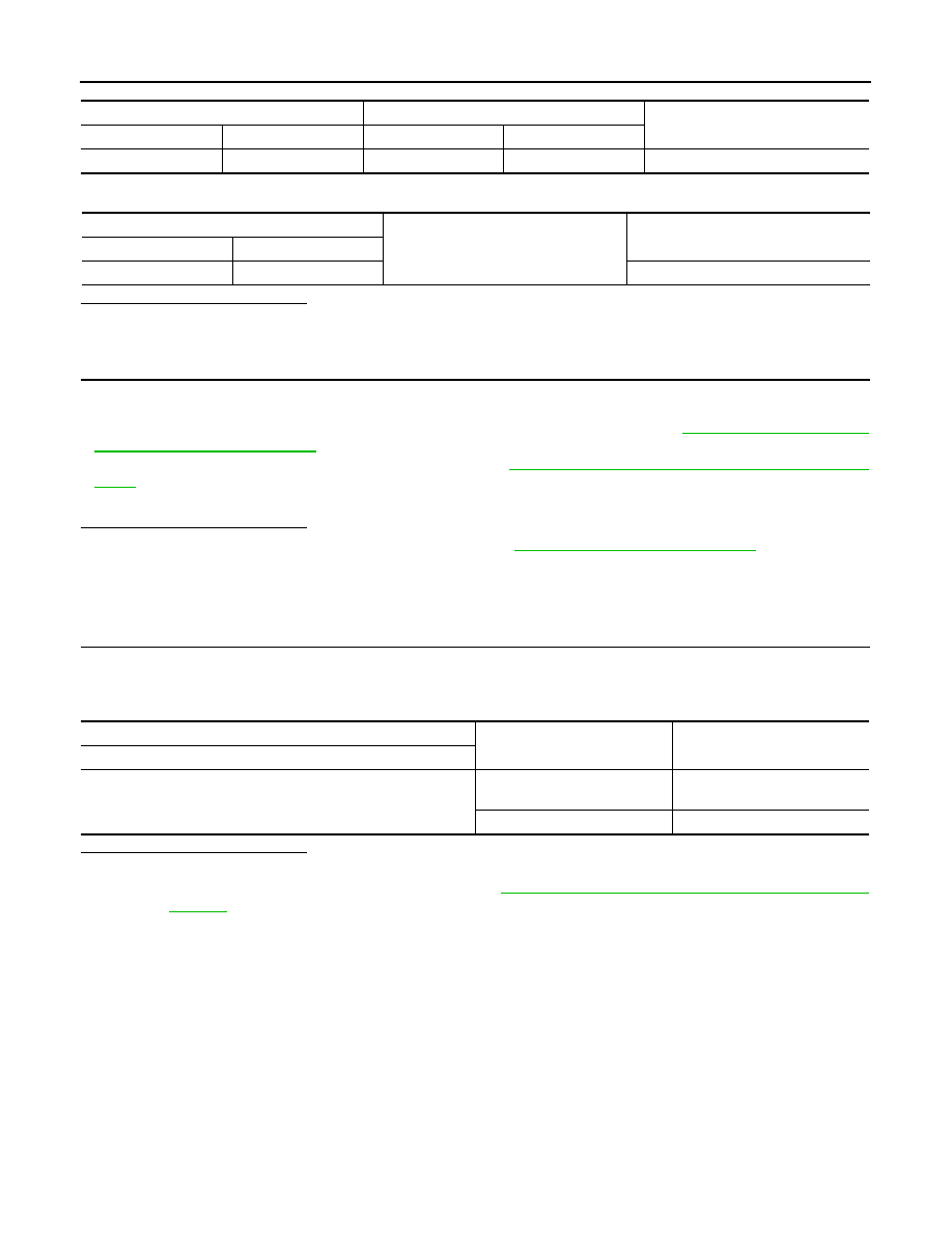
Component Inspection (Heated Steering Wheel Relay)
INFOID:0000000008459281
1.
CHECK HEATED STEERING WHEEL RELAY CONTINUITY
Check continuity between heated steering wheel relay terminals.
CAUTION:
Connect the fuse between the terminals when applying the voltage.
Is the inspection result normal?
YES
>> INSPECTION END
NO
>> Replace heated steering wheel relay. Refer to
ST-8, "Component Parts Location (Heated Steering
Fuse block (J/B)
Heated steering wheel switch
Continuity
Connector
Terminal
Connector
Terminal
M1
2A
M28
1
Existed
Fuse block (J/B)
Ground
Continuity
Connector
Terminal
M1
2A
Not existed
Heated steering wheel relay
Condition
Continuity
Terminal
3
−
5
6
−
7
Apply 12 V direct current be-
tween terminals 1 and 2.
Existed
Other conditions.
Not existed
Revision: 2012 September
2013 MURANO