Nissan Murano Z51 (2013 year). Manual - part 69
 

  Index      Manuals     Nissan Murano Z51 (2013 year) - Service and Repair Manual


Search            copyright infringement  


Content      ..     67      68      69      70     ..


Nissan Murano Z51 (2013 year). Manual - part 69


COLLISION DIAGNOSIS

SR-5

< BASIC INSPECTION >

[FOR USA AND CANADA]

C

D

E

F

G

I

J

K

L

M

A

B

SR

N

O

P

BASIC INSPECTION

COLLISION DIAGNOSIS

FOR FRONTAL COLLISION

FOR FRONTAL COLLISION : When SRS is activated in a collision

INFOID:0000000008457559

CAUTION:

Due to varying models and option levels, not all parts listed in the chart below apply to all vehicles.

WORK PROCEDURE

1.

Before performing any of the following steps, ensure that all vehicle body and structural repairs have been
completed.

2.

Replace the diagnosis sensor unit.

3.

Remove the front air bag modules, crash zone sensor, bracket and seat belt pre-tensioner assemblies.

4.

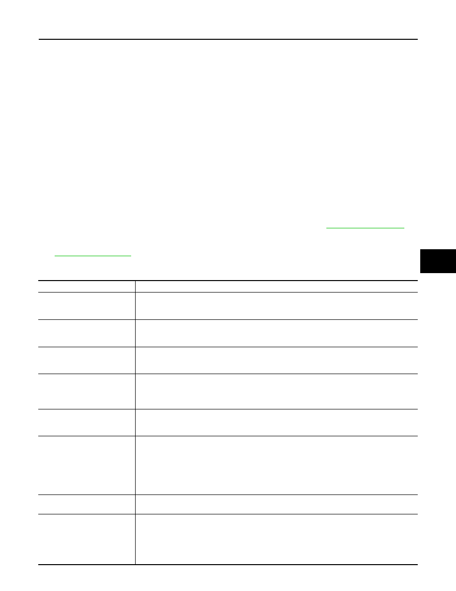
Check the SRS components using the table below:
Replace any SRS components showing visible signs of damage. (dents, cracks and deformation, etc.)

5.

Install new front air bag modules, crash zone sensor assembly, bracket and seat belt pre-tensioner
assemblies.

6.

Perform self-diagnosis using CONSULT or air bag warning lamp. Refer to 

SRC-15, "Description"

 for

details. Ensure entire SRS operates properly.

7.

After the work is completed, perform self-diagnosis to check that no malfunction is detected. Refer to

SRC-15, "Description"

.

SRS INSPECTION (FOR FRONTAL COLLISION)

Part

Inspection

Driver air bag module

If the driver air bag has deployed:
REPLACE
Install with new fasteners.

Front passenger air bag module 
(if equipped)

If the front passenger air bag has deployed:
REPLACE
Install with new fasteners.

Crash zone sensor

If any of the front air bags or seat belt pre-tensioners* have been activated:
REPLACE the crash zone sensor and bracket with new fasteners.
*: Confirm seat belt pre-tensioner activation using CONSULT only.

Seat belt pre-tensioner assem-
blies
(All applicable locations: buckle, 
retractor, lap outer)

If either the driver or passenger seat belt pre-tensioner* has been activated:
REPLACE all seat belt pre-tensioner assemblies with new fasteners.
*: Confirm seat belt pre-tensioner activation using CONSULT only.

Diagnosis sensor unit

If any of the SRS components have been activated:
REPLACE the diagnosis sensor unit.
Install with new fasteners.

Steering wheel

1.

Visually check steering wheel for deformities.

2.

Check harness (built into steering wheel) and connectors for damage, and terminals for defor-
mities.

3.

Install driver air bag module into the steering wheel to check fit and alignment with the wheel.

4.

Check steering wheel for excessive free play.

5.

If no damage is found, reinstall.

6.

If damaged 

 REPLACE.

Spiral cable

If the driver front air bag has deployed:
REPLACE the spiral cable.

Occupant classification system 
(Passenger seat)

1.

Remove passenger seat assembly.

2.

Check control unit case for dents, cracks of deformities.

3.

Check connectors and pressure sensor tube for damage, and terminals for deformities.

4.

Check seat frame and cushion pan for dents or deformities.

5.

If no damage is found, reinstall seat with new fasteners.

6.

If damaged 

 REPLACE seat cushion assembly with new fasteners.

Revision: 2012 September

2013 MURANO

SR-6

< BASIC INSPECTION >

[FOR USA AND CANADA]

COLLISION DIAGNOSIS

FOR FRONTAL COLLISION : When SRS is not activated in a collision

INFOID:0000000008457560

CAUTION:

Due to varying models and option levels, not all parts listed in the chart below apply to all vehicles.

WORK PROCEDURE

1.

Before performing any of the following steps, ensure that all vehicle body and structural repairs have been
completed.

2.

Check the SRS components using the table below:
Replace any SRS components showing visible signs of damage. (dents, cracks and deformation, etc.)

3.

Perform self-diagnosis using CONSULT or air bag warning lamp. Refer to 

SRC-15, "Description"

 for

details. Ensure entire SRS operates properly.

4.

After the work is completed, perform self-diagnosis to check that no malfunction is detected. Refer to

SRC-15, "Description"

.

SRS INSPECTION (FOR FRONTAL COLLISION)

Harness and connectors

1.

Check connectors for poor connection, damage, and terminals for deformities.

2.

Check harness for binding, chafing, cuts, or deformities.

3.

If no damage is found, reinstall the harness and connectors.

4.

If damaged 

 REPLACE the damaged harness. Do not attempt to repair, splice or modify any 

SRS harness.

Instrument panel assembly

If the front passenger air bag has deployed: 
REPLACE the instrument panel assembly. (integrated type)

Part

Inspection

Part

Inspection

Driver air bag module

If the driver air bag has NOT been deployed:
1.

Remove driver air bag module. Check harness cover and connectors for damage, terminals for 
deformities, and harness for binding.

2.

Install driver air bag module into the steering wheel to check fit and alignment with the wheel.

3.

If no damage is found, reinstall with new fasteners.

4.

If damaged 

 REPLACE. Install driver air bag module with new fasteners.

Front passenger air bag module 
(if equipped)

If the front passenger air bag has NOT been deployed:
1.

Remove front passenger air bag module. Check harness cover and connectors for damage, ter-
minals for deformities, and harness for binding.

2.

Install front passenger air bag module into the instrument panel to check fit with the instrument 
panel.

3.

If no damage is found, reinstall with new fasteners.

4.

If damaged 

 REPLACE. Install front passenger air bag modules with new fasteners.

Crash zone sensor

If the front air bags or seat belt pre-tensioners have NOT been activated:
1.

Remove the crash zone sensor. Check harness connectors for damage, terminals for deformi-
ties, and harness for binding.

2.

Check for visible signs of damage (dents, cracks, deformation, etc.) of the crash zone sensor 
and bracket.

3.

Install the crash zone sensor to check fit.

4.

If no damage is found, reinstall with new fasteners.

5.

If damaged 

 REPLACE the crash zone sensor and bracket with new fasteners. 

Seat belt pre-tensioner assem-
blies
(All applicable locations: buckle, 
retractor, lap outer)

If the pre-tensioners have NOT been activated:
1.

Remove seat belt pre-tensioners.
Check harness cover and connectors for damage, terminals for deformities, and harness for 
binding.

2.

Check belts for damage and anchors for loose mounting.

3.

Check retractor for smooth operation.

4.

Check seat belt adjuster for damage.

5.

Check for deformities of the center pillar inner.

6.

If the center pillar inner has no damage, REPLACE the seat belt pre-tensioner assembly.

7.

If no damage is found, reinstall seat belt pre-tensioner assembly.

8.

If damaged 

 REPLACE. Install the seat belt pre-tensioners with new fasteners. 

Revision: 2012 September

2013 MURANO

COLLISION DIAGNOSIS

SR-7

< BASIC INSPECTION >

[FOR USA AND CANADA]

C

D

E

F

G

I

J

K

L

M

A

B

SR

N

O

P

FOR SIDE AND ROLLOVER COLLISION

FOR SIDE AND ROLLOVER COLLISION : When SRS is activated in a collision

INFOID:0000000008457561

CAUTION:

Due to varying models and option levels, not all parts listed in the chart below apply to all vehicles.

WORK PROCEDURE

1.

Before performing any of the following steps, ensure that all vehicle body and structural repairs have been
completed.

2.

Replace the following components:
• Front seat back assembly (on the side on which side air bag is activated)
• Door finisher (on the side on which door-mounted curtain air bag is activated)
• Pop-up roll bar assemblies and pop-up roll bar covers
• Side air bag (satellite) sensor LH/RH (on the side on which side air bag is activated)
• Diagnosis sensor unit
• Seat belt pre-tensioner assemblies

3.

Check the SRS components and the related parts using the following table.
Replace any SRS components and the related parts showing visible signs of damage. (dents, cracks,
deformation, etc.)

4.

Perform self-diagnosis using CONSULT and “AIR BAG” warning lamp. Refer to 

SRC-15, "Description"

 for

details. Make sure entire SRS operates properly.

5.

After the work is completed, perform self-diagnosis to check that no malfunction is detected. Refer to

SRC-15, "Description"

.

Diagnosis sensor unit

If none of the SRS components have been activated:
1.

Check case for dents, cracks or deformities.

2.

Check connectors for damage, and terminals for deformities.

3.

If no damage is found, reinstall with new fasteners.

4.

If damaged 

 REPLACE. Install diagnosis sensor unit with new fasteners.

Steering wheel

1.

Visually check steering wheel for deformities.

2.

Check harness (built into steering wheel) and connectors for damage, and terminals for defor-
mities.

3.

Install driver air bag module into the steering wheel to check fit and alignment with the wheel.

4.

Check steering wheel for excessive free play.

5.

If no damage is found, reinstall.

6.

If damaged 

 REPLACE.

Spiral cable

If the driver front air bag has not deployed:
1.

Visually check spiral cable and combination switch for damage.

2.

Check connectors and protective tape for damage.

3.

Check steering wheel for noise, binding or heavy operation.

4.

If no damage is found, reinstall.

5.

If damaged 

 REPLACE.

Occupant classification system 
(Passenger seat)

1.

Remove passenger seat assembly.

2.

Check control unit case for dents, cracks of deformities.

3.

Check connectors and pressure sensor tube for damage, and terminals for deformities.

4.

Check seat frame and cushion pan for dents or deformities.

5.

If no damage is found, reinstall seat with new fasteners.

6.

If damaged 

 REPLACE seat cushion assembly with new fasteners.

Harness and connectors

1.

Check connectors for poor connection, damage, and terminals for deformities.

2.

Check harness for binding, chafing, cuts, or deformities.

3.

If no damage is found, reinstall the harness and connectors.

4.

If damaged 

 REPLACE the damaged harness. Do not attempt to repair, splice or modify any 

SRS harness.

Instrument panel assembly

If the front passenger air bag has NOT deployed:
1.

Visually check instrument panel assembly for damage.

2.

If no damage is found, reinstall the instrument panel assembly.

3.

If damaged 

 REPLACE the instrument panel assembly.

Part

Inspection

Revision: 2012 September

2013 MURANO

SR-8

< BASIC INSPECTION >

[FOR USA AND CANADA]

COLLISION DIAGNOSIS

SRS INSPECTION (FOR SIDE AND ROLLOVER COLLISION)

FOR SIDE AND ROLLOVER COLLISION : When SRS is not activated in a collision

INFOID:0000000008457562

CAUTION:

Due to varying models and option levels, not all parts listed in the chart below apply to all vehicles.

WORK PROCEDURE

1.

Before performing any of the following steps, ensure that all vehicle body and structural repairs have been
completed.

2.

Check the SRS components and the related parts using the following table.
• If the front seat back assembly is damaged, the front seat back assembly must be replaced.
• If the door finisher assembly is damaged, the door finisher assembly and door-mounted curtain air bag

module must be replaced.

3.

Perform self-diagnosis using CONSULT and “AIR BAG” warning lamp. Refer to 

SRC-15, "Description"

 for

details. Make sure entire SRS operates properly.

4.

After the work is completed, perform self-diagnosis to check that no malfunction is detected. Refer to

SRC-15, "Description"

.

SRS INSPECTION (FOR SIDE AND ROLLOVER COLLISION)

Part

Inspection

Side curtain air bag module LH

If the side curtain air bag LH has deployed:
REPLACE the side curtain air bag module LH.
Install with new fasteners.

Side curtain air bag module RH

If the side curtain air bag RH has deployed:
REPLACE the side curtain air bag module RH.
Install with new fasteners.

Front side air bag module LH

If the front side air bag LH has deployed: 
REPLACE front seatback assembly LH.

Front side air bag module RH

If the front side air bag RH has deployed:
REPLACE front seatback assembly RH.

Side air bag (satellite) sensor 
(LH or RH) 

If any of the SRS components have deployed:
REPLACE the side air bag (satellite) sensor on the collision side with new fasteners.

Diagnosis sensor unit

If any of the SRS components have deployed:
REPLACE the diagnosis sensor unit with new fasteners.

Seat belt pre-tensioner assem-
blies
(All applicable locations: buckle, 
retractor, lap outer)

If either the driver or passenger seat belt pre-tensioner* has been activated:
REPLACE all seat belt pre-tensioner assemblies with new fasteners.
*: Confirm seat belt pre-tensioner activation using CONSULT only.

Center inner pillar

1.

Check the center inner pillar on the collision side for damage (dents, cracks, deformation, etc.).

2.

If damaged 

 REPAIR the center inner pillar.

Trim/headlining

1.

Check for visible signs of damage (dents, cracks, deformation, etc.) of the interior trim on the 
collision side.

2.

If damaged 

 REPLACE the damaged trim parts.

Door-mounted curtain air bag 
module LH

If the door-mounted curtain air bag module LH has deployed:
REPLACE the door finisher LH and door-mounted curtain air bag module.
Install with new fasteners.

Door-mounted curtain air bag 
module RH

If the door-mounted curtain air bag module RH has deployed:
REPLACE the door finisher RH and door-mounted curtain air bag module.
Install with new fasteners.

Pop-up roll bar assemblies

If the pop-up roll bar has deployed:
REPLACE pop-up roll bar assemblies and pop-up roll bar covers.
Install with new fasteners.

Revision: 2012 September

2013 MURANO

COLLISION DIAGNOSIS

SR-9

< BASIC INSPECTION >

[FOR USA AND CANADA]

C

D

E

F

G

I

J

K

L

M

A

B

SR

N

O

P

Part

Inspection

Side curtain air bag module LH

If the side curtain air bag LH has NOT deployed:
1.

Check for visible signs of damage (dents, tears, deformation, etc.) of the center pillar on the col-
lision side.

2.

If damaged 

 Remove the side curtain air bag module LH.

3.

Check for visible signs of damage (tears etc.) of the side curtain air bag module LH.

4.

Check harness and connectors for damage, and terminals for deformities.

5.

If no damage is found, reinstall the side curtain air bag module LH with new fasteners.

6.

If damaged 

 REPLACE the side curtain air bag module LH with new fasteners. 

Side curtain air bag module RH

If the side curtain air bag RH has NOT deployed:
1.

Check for visible signs of damage (dents, tears, deformation, etc.) of the center pillar on the col-
lision side.

2.

If damaged 

 Remove the side curtain air bag module RH.

3.

Check for visible signs of damage (tears etc.) of the side curtain air bag module RH.

4.

Check harness and connectors for damage, and terminals for deformities.

5.

If no damage is found, reinstall the side curtain air bag module RH with new fasteners.

6.

If damaged 

 REPLACE the side curtain air bag module RH with new fasteners. 

Front side air bag module LH

If the front side air bag LH has NOT deployed: 
1.

Check for visible signs of damage (dents, tears, deformation, etc.) of the seat back on the col-
lision side.

2.

Check harness and connectors for damage, and terminals for deformities.

3.

If damaged 

 REPLACE the front seatback assembly LH. 

Front side air bag module RH

If the front side air bag RH has NOT deployed:
1.

Check for visible signs of damage (dents, tears, deformation, etc.) of the seat back on the col-
lision side.

2.

Check harness and connectors for damage, and terminals for deformities.

3.

If damaged 

 REPLACE the front seatback assembly RH. 

Side air bag (satellite) sensor 
(LH or RH) 

If none of the SRS components have been activated:
1.

Remove the side air bag (satellite) sensor (LH or RH) on the collision side. Check harness con-
nectors for damage, terminals for deformities, and harness for binding.

2.

Check for visible signs of damage (dents, cracks, deformation, etc.) of the side air bag (satellite) 
sensor (LH or RH).

3.

Install the side air bag (satellite) sensor (LH or RH) to check fit.

4.

If no damage is found, reinstall the side sir bag (satellite) sensor (LH or RH) with new fasteners.

5.

If damaged 

 REPLACE the side air bag (satellite) sensor (LH or RH) with new fasteners.

Diagnosis sensor unit

If none of the SRS components have been activated:
1.

Check case and bracket for dents, cracks or deformities.

2.

Check connectors for damage, and terminals for deformities.

3.

If no damage is found, reinstall the diagnosis sensor unit with new fasteners.

4.

If damaged 

 REPLACE the diagnosis sensor unit with new fasteners.

Seat belt pre-tensioner assem-
blies
(All applicable locations: buckle, 
retractor, lap outer)

If the pre-tensioners have NOT been activated:
1.

Remove seat belt pre-tensioners.
Check harness cover and connectors for damage, terminals for deformities, and harness for 
binding.

2.

Check belts for damage and anchors for loose mounting.

3.

Check retractor for smooth operation.

4.

Check seat belt adjuster for damage.

5.

Check for deformities of the center pillar inner.

6.

If the center pillar inner has no damage, REPLACE the seat belt pre-tensioner assembly.

7.

If no damage is found, reinstall seat belt pre-tensioner assembly.

8.

If damaged 

 REPLACE. Install the seat belt pre-tensioners with new fasteners. 

Seat (with front side air bag)

If the front LH or front RH side air bag modules have NOT deployed: 
1.

Visually check the seat on the collision side.

2.

Remove the seat on the collision side and check the following for damage and deformities.

-

Harness, connectors and terminals

-

Frame and recliner (for front and rear seat), and also adjuster and slides (for front seat)

3.

If no damage is found, reinstall the seat.

4.

If damaged 

 REPLACE the damaged seat parts using new fasteners. If the front seat back is 

damaged, the front seat back assembly must be replaced.

Center inner pillar

1.

Check the center inner pillar on the collision side for damage (dents, cracks, deformation, etc.).

2.

If damaged 

 REPAIR the center inner pillar.

Revision: 2012 September

2013 MURANO

SR-10

< BASIC INSPECTION >

[FOR USA AND CANADA]

COLLISION DIAGNOSIS

Trim/headlining

1.

Check for visible signs of damage (dents, cracks, deformation, etc.) of the interior trim on the 
collision side.

2.

If damaged 

 REPLACE the damaged trim parts.

Door-mounted curtain air bag 
module LH

If the door-mounted curtain air bag LH has NOT deployed:
1.

Check for visible signs of damage (dents, tears, deformation, etc.) of the door finisher on the 
collision side.

2.

If damaged 

 REPLACE the door finisher LH with new fasteners. 

3.

Check for visible signs of damaged (tears etc.) of the door-mounted curtain air bag module LH.

4.

Check harness and connectors for damage, and terminals for deformities.

5.

If no damage is found, reinstall door finisher.

CAUTION:

When removing door-mounted curtain air bag module from door finisher, never reuse 
door finisher.

6.

If damaged 

 REPLACE the door finisher LH and door-mounted curtain air bag module LH with 

new fasteners. 

Door-mounted curtain air bag 
module RH

If the door-mounted curtain air bag RH has NOT deployed:
1.

Check for visible signs of damage (dents, tears, deformation, etc.) of the door finisher on the 
collision side.

2.

If damaged 

 REPLACE the door finisher RH with new fasteners.

3.

Check for visible signs of damage (tears etc.) of the door-mounted curtain air bag module RH.

4.

Check harness and connectors for damage, and terminals for deformities.

5.

If no damage is found, reinstall door finisher.

CAUTION:

When removing door-mounted curtain air bag module from door finisher, never reuse 
door finisher.

6.

If damaged 

 REPLACE the door finisher RH and door-mounted curtain air bag module RH with 

new fasteners. 

Pop-up roll bar

If the pop-up roll bar has NOT deployed:
1.

Check for visible signs of damage (dents, tears, deformation, etc.) of the pop-up roll bar.

2.

If damaged 

 REPLACE the pop-up roll bar with new fasteners.

3.

Check harness and connectors for damage, and terminals for deformities.

4.

If no damage is found, reinstall the pop-up roll bar with new fasteners.

5.

Check for visible signs of damage (dents, cracks, deformation, etc.) of the seatback support 
brace assembly.

6.

If damaged 

 REPAIR the seatback support brace assembly.

Part

Inspection

Revision: 2012 September

2013 MURANO

DRIVER AIR BAG MODULE

SR-11

< REMOVAL AND INSTALLATION >

[FOR USA AND CANADA]

C

D

E

F

G

I

J

K

L

M

A

B

SR

N

O

P

REMOVAL AND INSTALLATION

DRIVER AIR BAG MODULE

Exploded View

INFOID:0000000008457563

Removal and Installation

INFOID:0000000008457564

WARNING:

• Before servicing, turn ignition switch OFF, disconnect battery negative terminal and wait 3 minutes

or more.

• Always work from the side of air bag module. Never work in front of it.
• Never use the air tools or electric tools for servicing.

REMOVAL

1.

Remove the side lids (LH and RH).

2.

Remove the TORX bolts (LH and RH) from the steering wheel
(1) lower side using TORX bit (A).

3.

Pull out the driver air bag module.

1.

Steering wheel

2.

Driver air bag module

3.

Side lid (LH/RH)

4.

TORX bolt (LH/RH)

: Always replace after every disassembly.

: N·m (kg-m, in-lb)

JMHIA0503GB

JMHIA0265ZZ

Revision: 2012 September

2013 MURANO

SR-12

< REMOVAL AND INSTALLATION >

[FOR USA AND CANADA]

DRIVER AIR BAG MODULE

4.

Disconnect the driver air bag harness connector.

CAUTION:

• For installing/removing the driver air bag harness connec-

tor, insert thin screwdriver wrapped in tape into notch, lift
lock and remove the connector.

• Install the connector with lock raised, and push lock into

the connector.

• After installing the connector, check that the lock is

pushed securely into it.

5.

Remove the driver air bag module.

CAUTION:

• Always place the driver air bag module with pad side facing

upward.

• Never impact the driver air bag module.
• Replace the driver air bag module if it has been dropped or

sustained an impact.

• Never insert any foreign objects (screwdriver, etc.) into the driver air bag module.
• Never disassemble the driver air bag module.
• Never expose the driver air bag module to temperatures exceeding 90 

°

C (194 

°

F).

• Never allow oil, grease, detergent, or water to come in contact with the driver air bag module.

INSTALLATION

Install in the reverse order of removal.

CAUTION:

• Never use the old TORX bolts after removal, replace with the new bolts.
• Fix the driver air bag harness to the harness fixing hook (A).

PHIA0953J

: Upward

JMHIA0504ZZ

JMHIA0009ZZ

JMHIA0505ZZ

Revision: 2012 September

2013 MURANO

DRIVER AIR BAG MODULE

SR-13

< REMOVAL AND INSTALLATION >

[FOR USA AND CANADA]

C

D

E

F

G

I

J

K

L

M

A

B

SR

N

O

P

• Tighten the TORX bolts after completely adjusting the centers of fixing holes on the driver air bag

module side and the steering wheel side. If the holes are misaligned, the bolt threads are damaged
and the module is not installed securely.

• If malfunction is detected by the air bag warning lamp, after repair or replacement of the malfunc-

tioning parts, reset the memory using self-diagnosis or CONSULT. Refer to 

SRC-15, "Description"

.

• After the work is completed, check that no system malfunction is detected by air bag warning lamp. 

Revision: 2012 September

2013 MURANO

SR-14

< REMOVAL AND INSTALLATION >

[FOR USA AND CANADA]

SPIRAL CABLE

SPIRAL CABLE

Exploded View

INFOID:0000000008457565

Removal and Installation

INFOID:0000000008457566

WARNING:

• Before servicing, turn ignition switch OFF, disconnect battery negative terminal and wait 3 minutes

or more.

• Never use the air tools or electric tools for servicing.

REMOVAL

1.

Remove the driver air bag module. Refer to 

SR-11, "Removal and Installation"

.

2.

Remove the steering wheel. Refer to 

ST-34, "Removal and Installation"

.

3.

Remove the steering column cover (upper/lower). Refer to 

IP-12, "Exploded View"

.

4.

Disconnect the spiral cable and steering angle sensor harness
connectors (A).
NOTE:
Disconnect the spiral cable and steering angle sensor body side
harness connectors after removing the spiral cable.

5.

Remove the spiral cable fixing screws.

1.

Steering column cover (upper)

2.

Spiral cable

3.

Steering column cover (lower)

4.

Steering column assembly

A

: Driver air bag harness connector

JMHIA0506ZZ

JMHIA0507ZZ

Revision: 2012 September

2013 MURANO

SPIRAL CABLE

SR-15

< REMOVAL AND INSTALLATION >

[FOR USA AND CANADA]

C

D

E

F

G

I

J

K

L

M

A

B

SR

N

O

P

6.

Remove the spiral cable side pawls (A).

7.

Pull out forward the spiral cable. 

8.

Remove the steering angle sensor. Refer to 

BRC-128, "Removal and Installation"

.

CAUTION:

• Never impact the spiral cable.
• Never impact the spiral cable by dropping, etc. Replace the

spiral cable if it has been dropped or sustained an impact.

• Never disassemble the spiral cable.
• Never apply lubricant to the spiral cable.
• Never allow oil, grease, detergent, or water to come in contact with the spiral cable.

INSTALLATION

Install in the reverse order of removal.

CAUTION:

• The spiral cable may snap during steering operation if the

cable is installed in an improper position. 
The neutral position is set as per the following.

• Turn carefully the spiral cable clockwise to the end position.

Then turn it counterclockwise (about 2 and a half turns) and
stop turning at the mark (B) on which the stopper insertion
holes are in the same position.

• The service part is installed in the neutral position by the

stopper and can be set without adjusting after the stopper is
removed.

• Never over turn the spiral cable or go beyond number of turns

required. (This will cause the cable to snap.)

• Adjust the spiral cable locating pin (A) to the steering wheel

locating pin hole (C).

JMHIA0508ZZ

JMHIA0009ZZ

JMHIA0657ZZ

Revision: 2012 September

2013 MURANO

SR-16

< REMOVAL AND INSTALLATION >

[FOR USA AND CANADA]

SPIRAL CABLE

• If malfunction is detected by the air bag warning lamp, after repair or replacement of the malfunc-

tioning parts, reset the memory using self-diagnosis or CONSULT. Refer to 

SRC-15, "Description"

.

• After the work is completed, check that no system malfunction is detected by air bag warning lamp. 

Revision: 2012 September

2013 MURANO

FRONT PASSENGER AIR BAG MODULE

SR-17

< REMOVAL AND INSTALLATION >

[FOR USA AND CANADA]

C

D

E

F

G

I

J

K

L

M

A

B

SR

N

O

P

FRONT PASSENGER AIR BAG MODULE

Exploded View

INFOID:0000000008457567

Removal and Installation

INFOID:0000000008457568

WARNING:

• Before servicing, turn ignition switch OFF, disconnect battery negative terminal and wait 3 minutes

or more.

• Always work from the side of air bag module. Never work in front of it.
• Never use the air tools or electric tools for servicing.

REMOVAL

1.

Remove the glove box lid assembly. Refer to 

IP-13, "Removal and Installation"

.

2.

Remove the Instrument lower assist panel. Refer to 

IP-13, "Removal and Installation"

.

3.

Disconnect the front passenger air bag harness connector (A).

4.

Remove the front passenger air bag module fixing bolt (B).
NOTE:
The figure shows the installed front passenger air bag module.
(Under view of the module installed without glove box cover.)

5.

Remove the instrument panel assembly (1). Refer to 

IP-13, "Removal and Installation"

.

1.

Instrument panel assembly

2.

Front passenger air bag module

: Always replace after every disassembly.

: N·m (kg-m, ft-lb)

JMHIA0509GB

JMHIA0510ZZ

Revision: 2012 September

2013 MURANO

SR-18

< REMOVAL AND INSTALLATION >

[FOR USA AND CANADA]

FRONT PASSENGER AIR BAG MODULE

6.

Remove the front passenger air bag module fixing screws (B).

7.

Disconnect the pawls (C) by using remover tool (A), and then
remove the front passenger air bag module (2) from instrument
panel.

CAUTION:

• Always place the front passenger air bag module with pad

side facing upward.

• Never impact the passenger air bag module.
• Replace the front passenger air bag module if it has been

dropped or sustained an impact.

• Never insert any foreign objects (screwdriver, etc.) into front passenger air bag module.
• Never disassembly the front passenger air bag module.
• Never expose the front passenger air bag module to temperatures exceeding 90 

°

C (194 

°

F).

• Never allow oil, grease, detergent, or water to come in contact with the front passenger air bag mod-

ule.

INSTALLATION

Install in the reverse order of removal.

CAUTION:

• Never use the old fixing bolts after removal, replace with the new bolts.
• Never damage the harness while installing.
• If malfunction is detected by the air bag warning lamp, after repair or replacement of the malfunc-

tioning parts, reset the memory using self-diagnosis or CONSULT. Refer to 

SRC-15, "Description"

.

• After the work is completed, check that no system malfunction is detected by air bag warning lamp. 

JMHIA0511ZZ

: Upward

JMHIA0512ZZ

JMHIA0009ZZ

Revision: 2012 September

2013 MURANO

SIDE CURTAIN AIR BAG MODULE

SR-19

< REMOVAL AND INSTALLATION >

[FOR USA AND CANADA]

C

D

E

F

G

I

J

K

L

M

A

B

SR

N

O

P

SIDE CURTAIN AIR BAG MODULE

Exploded View

INFOID:0000000008457569

Removal and Installation

INFOID:0000000008457570

WARNING:

• Before servicing, turn ignition switch OFF, disconnect battery negative terminal and wait 3 minutes

or more.

• Always work from the side of air bag module. Never work in front of it.
• Never use air tools or electric tools for servicing.

REMOVAL

1.

Remove the headlining. 
• Normal roof models: Refer to 

INT-25, "NORMAL ROOF : Removal and Installation"

.

• Sunroof models: Refer to 

INT-29, "SUNROOF : Removal and Installation"

.

2.

Remove the side curtain air bag harness connector.

CAUTION:

• For installing/removing the side curtain air bag harness

connector, insert thin screwdriver wrapped in tape into
notch, lift lock and remove the connector.

• Install the connector with lock raised, and push lock into

the connector.

• After installing the connector, check that the lock is

pushed securely into it.

1.

Side curtain air bag inflator

: N·m (kg-m, ft-lb)

JMHIA1684GB

PHIA0953J

Revision: 2012 September

2013 MURANO

SR-20

< REMOVAL AND INSTALLATION >

[FOR USA AND CANADA]

SIDE CURTAIN AIR BAG MODULE

3.

Remove the fixing bolts, and then remove the side curtain air bag module.

CAUTION:

• Never impact the side curtain air bag module.
• Replace the side curtain air bag module if it has been dropped

or sustained an impact. 

• Never insert any foreign objects (screwdriver, etc.) into the side curtain air bag module.
• Never disassemble the side curtain air bag module.
• Never expose the side curtain air bag module to temperatures exceeding 90 

°

C (194 

°

F).

• Never allow oil, grease, detergent, or water to come in contact with the side curtain air bag module.

INSTALLATION

Install in the reverse order of removal.

CAUTION:

• If malfunction is detected by the air bag warning lamp, after repair or replacement of the malfunc-

tioning parts, reset the memory using self-diagnosis or CONSULT. Refer to 

SRC-15, "Description"

.

• After the work is completed, check that no system malfunction is detected by air bag warning lamp. 

JMHIA0009ZZ

Revision: 2012 September

2013 MURANO


Content      ..     67      68      69      70     ..