Nissan Murano Z51 (2013 year). Manual - part 60
REAR POWER WINDOW SWITCH
PWC-19
< DTC/CIRCUIT DIAGNOSIS >
C
D
E
F
G
H
I
J
L
M
A
B
PWC
N
O
P
Is the inspection result normal?
YES
>> Replace power window main switch. Refer to
PWC-92, "Removal and Installation"
NO
>> Repair or replace harness.
3.
CHECK REAR POWER WINDOW SWITCH
Check rear power window switch.
Refer to
PWC-19, "Component Inspection"
Is the inspection result normal?
YES
>> GO TO 4.
NO
>> Replace rear power window switch. Refer to
PWC-92, "Removal and Installation"
4.
CHECK INTERMITTENT INCIDENT
GI-45, "Intermittent Incident"
.
>> INSPECTION END
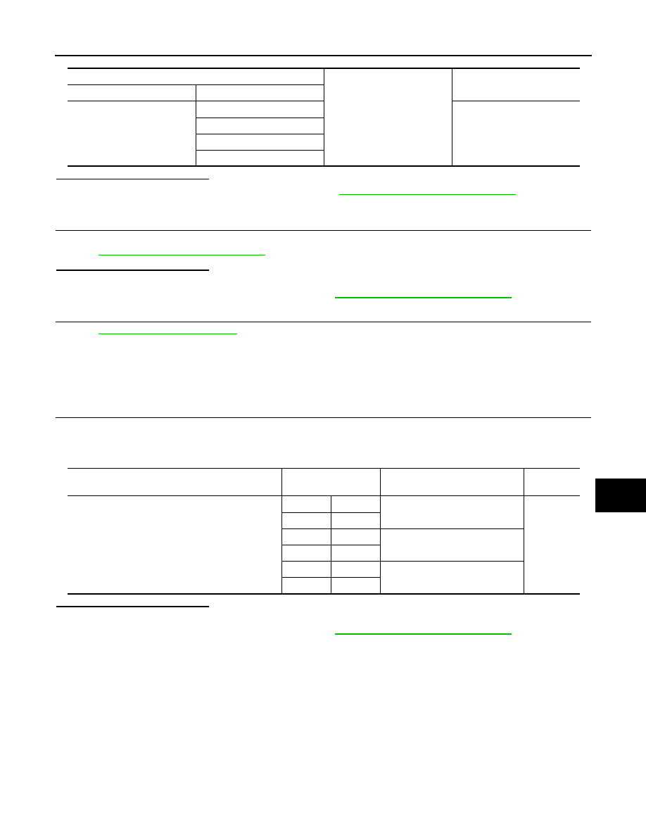
Component Inspection
INFOID:0000000008458018
1.
CHECK REAR POWER WINDOW SWITCH
1.
Turn ignition switch OFF.
2.
Disconnect rear power window switch connector.
3.
Check rear power window switch terminals.
Is the inspection result normal?
YES
>> INSPECTION END
NO
>> Replace rear power window switch. Refer to
PWC-92, "Removal and Installation"
Power window main switch
Ground
Continuity
Connector
Terminal
D5
1
Not existed
3
5
7
Rear power window switch
Terminal
Rear power window switch condi-
tion
Continuity
D83 (LH)
D103 (RH)
1
5
UP
Existed
3
4
3
4
NEUTRAL
2
5
1
4
DOWN
2
5
Revision: 2012 September
2013 MURANO