Nissan Murano Z51 (2013 year). Manual - part 54
PCS
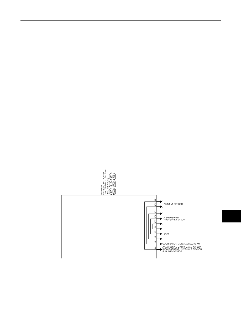
IPDM E/R (INTELLIGENT POWER DISTRIBUTION MODULE ENGINE ROOM)
PCS-29
< ECU DIAGNOSIS INFORMATION >
[IPDM E/R]
C
D
E
F
G
H
I
J
K
L
B
A
O
P
N
Fail-safe
INFOID:0000000008455187
CAN COMMUNICATION CONTROL
When CAN communication with ECM and BCM is impossible, IPDM E/R performs fail-safe control. After CAN
communication recovers normally, it also returns to normal control.
If No CAN Communication Is Available With ECM
JRMWC5031GB
Revision: 2012 September
2013 MURANO