Nissan Murano Z51 (2013 year). Manual - part 44
MIR-44
< REMOVAL AND INSTALLATION >
[WITH ADP]
INSIDE MIRROR
REMOVAL AND INSTALLATION
INSIDE MIRROR
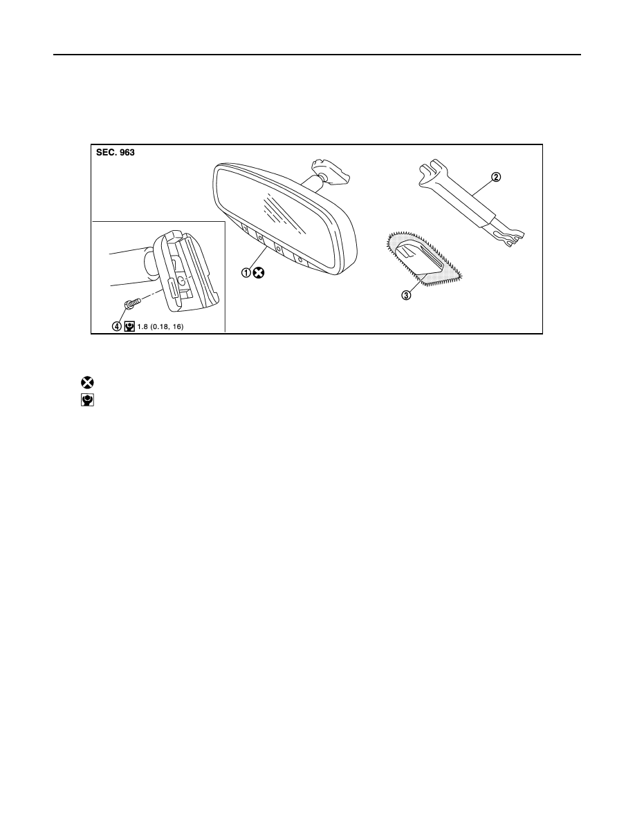
Exploded View
INFOID:0000000008455791
Removal and Installation
INFOID:0000000008455792
CAUTION:
Never reuse the inside mirror disassembled from mirror base.
REMOVAL
1.
Remove the inside mirror cover.
2.
Remove TORX bolt.
3.
Slide the inside mirror upward to remove.
INSTALLATION
Install in the reverse order of removal.
CAUTION:
When inserting the inside mirror into the mirror base, be sure to push the pawl until it get connected to
the mirror base.
1.
Inside mirror
2.
Inside mirror cover
3.
Mirror base
4.
TORX bolt
: Always replace after every disassembly.
: N·m (kg-m, in-lb)
JMLIA0136GB
Revision: 2012 September
2013 MURANO