Nissan Murano Z51 (2013 year). Manual - part 32


  Index      Manuals     Nissan Murano Z51 (2013 year) - Service and Repair Manual


Search            copyright infringement  


Content      ..     30      31      32      33     ..


Nissan Murano Z51 (2013 year). Manual - part 32


QUICK REFERENCE CHART MURANO

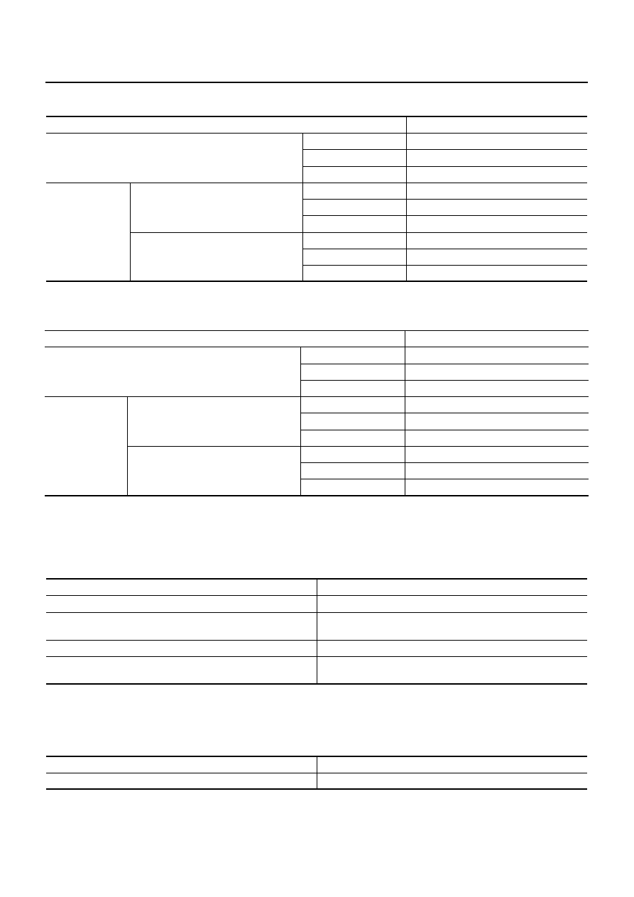
REAR WHEEL ALIGNMENT

ELS0003Y

FOR USA AND MEXICO MODELS

Measure value under unladen* conditions.
* : Fuel, engine coolant and lubricant are full. Spare tire, jack, hand tools and mats are in designated positions.

FOR CANADA MODELS

Measure value under unladen* conditions.
* : Fuel, engine coolant and lubricant are full. Spare tire, jack, hand tools and mats are in designated positions.

BRAKE PEDAL

ELS0003Z

Unit: mm (in)

BRAKE BOOSTER

Vacuum type

Unit: mm (in)

Item

Standard

Camber
Degree minute (Decimal degree)

Minimum

–1

°

 13

 (–1.21

°

)

Nominal

–0

°

 43

 (–0.72

°

)

Maximum

–0

°

 13

 (–0.21

°

)

Toe-in

Total toe-in
Distance

Minimum

In 0.9 mm (0.035 in)

Nominal

In 2.7 mm (0.106 in)

Maximum

In 4.5 mm (0.177 in)

Total toe-angle
Degree minute (Decimal degree)

Minimum

In 0

°

 04

 (In 0.07

°

)

Nominal

In 0

°

 12

 (In 0.20

°

)

Maximum

In 0

°

 20

 (In 0.33

°

)

Item

Standard

Camber
Degree minute (Decimal degree)

Minimum

–1

°

 11

 (–1.18

°

)

Nominal

–0

°

 41

 (–0.68

°

)

Maximum

–0

°

 11

 (–0.18

°

)

Toe-in

Total toe-in
Distance

Minimum

In 0.9 mm (0.035 in)

Nominal

In 2.7 mm (0.106 in)

Maximum

In 4.5 mm (0.177 in)

Total toe-angle
Degree minute (Decimal degree)

Minimum

In 0

°

 04

 (In 0.07

°

)

Nominal

In 0

°

 12

 (In 0.20

°

)

Maximum

In 0

°

 20

 (In 0.33

°

)

Item

Standard

Brake pedal height

197.1 - 207.1 (7.76 - 8.15)

Clearance between the stop lamp switch and ASCD brake switch 
threaded end

0.20 - 1.96 (0.0079 - 0.0772)

Brake pedal play

3.0 - 11.0 (0.118 - 0.433)

Depressed brake pedal height
[Depressing 490 N (50 kg, 110 lb) while turning the engine ON]

128 (5.04) or more

Item

Standard

Input rod length

127 (5.00)

2013

QUICK REFERENCE CHART MURANO

FRONT DISC BRAKE

Unit: mm (in)

REAR DISC BRAKE

Unit: mm (in)

REFILL CAPACITIES

ELS00040

Item

Limit

Brake pad

Wear thickness

2.0 (0.079)

Disc rotor

Wear thickness

26.0 (1.024)

Thickness variation (measured at 8 positions)

0.008 (0.0003)

Runout (with it attached to the vehicle)

0.040 (0.0016) or less

Item

Limit

Brake pad

Wear thickness

2.0 (0.079)

Disc rotor

Wear thickness

14.0 (0.551)

Thickness variation (measured at 8 positions)

0.020 (0.0008)

Runout (with it attached to the vehicle)

0.050 (0.0020) or less

UNIT

Liter

US measure

Fuel tank

82

21-5/8 gal

Coolant ( With reservoir tank at “MAX” level )

9.0

9-1/2 qt

Engine

Drain and refill

With oil filter change

4.6

4-7/8 qt

Without oil filter change

4.3

4-1/2 qt

Dry engine (Overhaul)

5.3

5-5/8 qt

Transmission

CVT

10.2

10-3/4 qt

Transfer

0.31

5/8 pt

Final drive

0.55

1-1/8 pt

Power steering system

1.0

1-1/8 qt

Air conditioning system

Compressor oil

0.15

5.07 fl oz

Refrigerant

0.60 kg

1.32 lb

2013

GI-1

GENERAL INFORMATION

C

D

E

F

G

H

I

J

K

L

M

B

GI

SECTION 

GI

N

O

P

CONTENTS

GENERAL INFORMATION

HOW TO USE THIS MANUAL ......................

3

HOW TO USE THIS MANUAL  ............................

3

Description ................................................................

3

Terms ........................................................................

3

Units ..........................................................................

3

Contents ....................................................................

3

Relation between Illustrations and Descriptions  .......

4

Components ..............................................................

4

HOW TO FOLLOW TROUBLE DIAGNOSES .....

6

Description ................................................................

6

How to Follow Test Groups in Trouble Diagnosis ......

6

Key to Symbols Signifying Measurements or Pro-
cedures ...................................................................
..

7

HOW TO READ WIRING DIAGRAMS  ................

9

Connector Symbols ...................................................

9

Sample/Wiring Diagram -Example-  .........................

10

Connector Information .............................................

12

ABBREVIATIONS ..............................................

14

Abbreviation List ......................................................

14

TIGHTENING TORQUE OF STANDARD 
BOLTS ................................................................

19

Description ..............................................................

19

Tightening Torque Table (New Standard Includ-
ed) ...........................................................................

19

RECOMMENDED CHEMICAL PRODUCTS 
AND SEALANTS ................................................

22

Recommended Chemical Products and Sealants 

....

22

VEHICLE INFORMATION ............................

23

IDENTIFICATION INFORMATION  .....................

23

Model Variation  .......................................................

23

Information About Identification or Model Code  ......

24

Dimensions .............................................................

27

Wheels & Tires ........................................................

27

PRECAUTION ..............................................

29

PRECAUTIONS .................................................

29

Description ...............................................................

29

FOR USA AND CANADA  ..........................................

29

FOR USA AND CANADA : Precaution for Supple-
mental Restraint System (SRS) "AIR BAG" and 
"SEAT BELT PRE-TENSIONER" ............................

29

FOR USA AND CANADA : Precautions For Xenon 
Headlamp Service  ...................................................

29

FOR USA AND CANADA : Precaution for Proce-
dure without Cowl Top Cover  ..................................

30

FOR MEXICO .............................................................

30

FOR MEXICO : Precaution for Supplemental Re-
straint System (SRS) "AIR BAG" and "SEAT BELT 
PRE-TENSIONER" ..................................................

30

FOR MEXICO : Precautions For Xenon Headlamp 
Service .....................................................................

30

FOR MEXICO : Precaution for Procedure without 
Cowl Top Cover .......................................................

31

Cautions in Removing Battery Terminal and AV 
Control Unit (Models with AV Control Unit)  .............

31

General Precautions ................................................

31

Three Way Catalyst  .................................................

33

Multiport Fuel Injection System or Engine Control 
System .....................................................................

33

Hoses ......................................................................

33

Engine Oils  ..............................................................

34

Air Conditioning  .......................................................

34

Fuel ..........................................................................

35

LIFTING POINT .................................................

36

Commercial Service Tools .......................................

36

Garage Jack and Safety Stand and 2-Pole Lift  .......

36

Board-On Lift  ...........................................................

37

TOW TRUCK TOWING  .....................................

38

Tow Truck Towing  ...................................................

38

Vehicle Recovery (Freeing a Stuck Vehicle)  ...........

39

Revision: 2012 September

2013 MURANO

HOW TO USE THIS MANUAL

GI-3

< HOW TO USE THIS MANUAL >

C

D

E

F

G

H

I

J

K

L

M

B

GI

N

O

P

HOW TO USE THIS MANUAL

HOW TO USE THIS MANUAL

Description

INFOID:0000000008457869

This volume explains “Removal, Disassembly, Installation, Inspection and Adjustment” and “Trouble Diag-
noses”.

Terms

INFOID:0000000008457870

• The captions WARNING and CAUTION warn you of steps that must be followed to prevent personal injury

and/or damage to some part of the vehicle.
WARNING indicates the possibility of personal injury if instructions are not followed.
CAUTION indicates the possibility of component damage if instructions are not followed.
BOLD TYPED STATEMENTS except WARNING and CAUTION give you helpful information.
Standard value: Tolerance at inspection and adjustment.
Limit value: The maximum or minimum limit value that should not be exceeded at inspection and adjust-
ment.

Units

INFOID:0000000008457871

• The UNITS given in this manual are primarily expressed as the SI UNIT (International System of Unit), and

alternatively expressed in the metric system and in the yard/pound system.
Also with regard to tightening torque of bolts and nuts, there are descriptions both about range and about the
standard tightening torque.

“Example”
Range

Standard

Contents

INFOID:0000000008457872

• A QUICK REFERENCE INDEX, a black tab (e.g. 

) is provided on the first page. You can quickly find the

first page of each section by matching it to the section's black tab.

• THE CONTENTS are listed on the first page of each section.
• THE TITLE is indicated on the upper portion of each page and shows the part or system.
• THE PAGE NUMBER of each section consists of two or three letters which designate the particular section

and a number (e.g. “BR-5”).

• THE SMALL ILLUSTRATIONS show the important steps such as inspection, use of special tools, knacks of

work and hidden or tricky steps which are not shown in the previous large illustrations.
Assembly, inspection and adjustment procedures for the complicated units such as the automatic transaxle
or transmission, etc. are presented in a step-by-step format where necessary.

Outer Socket Lock Nut

: 59 - 78 N·m (6.0 - 8.0 kg-m, 43 - 58 ft-lb)

Drive Shaft Installation Bolt

: 44.3 N·m (4.5 kg-m, 33 ft-lb)

Revision: 2012 September

2013 MURANO

GI-4

< HOW TO USE THIS MANUAL >

HOW TO USE THIS MANUAL

Relation between Illustrations and Descriptions

INFOID:0000000008457873

The following sample explains the relationship between the part description in an illustration, the part name in
the text and the service procedures.

Components

INFOID:0000000008457874

• THE LARGE ILLUSTRATIONS are exploded views (see the following) and contain tightening torques, lubri-

cation points, section number of the PARTS CATALOG (e.g. SEC. 440) and other information necessary to
perform repairs.
The illustrations should be used in reference to service matters only. When ordering parts, refer to the appro-
priate PARTS CATALOG.
Components shown in an illustration may be identified by a circled number. When this style of illustration is
used, the text description of the components will follow the illustration.

SAIA0519E

Revision: 2012 September

2013 MURANO

HOW TO USE THIS MANUAL

GI-5

< HOW TO USE THIS MANUAL >

C

D

E

F

G

H

I

J

K

L

M

B

GI

N

O

P

SYMBOLS

1.

Union bolt

2.

Copper washer

3.

Brake hose

4.

Cap

5.

Bleed valve

6.

Sliding pin bolt

7.

Piston seal

8.

Piston

9.

Piston boot

10.

Cylinder body

11.

Sliding pin

12.

Torque member mounting bolt

13.

Washer

14.

Sliding pin boot

15.

Bushing

16.

Torque member

17.

Inner shim cover

18.

Inner shim

19.

Inner pad

20.

Pad retainer

21.

Pad wear sensor

22.

Outer pad

23.

Outer shim

24.

Outer shim cover

1: PBC (Poly Butyl Cuprysil) grease 
or silicone-based grease

2: Rubber grease

: Brake fluid

Refer to GI section for additional symbol definitions.

SFIA2959E

SAIA0749E

Revision: 2012 September

2013 MURANO

GI-6

< HOW TO USE THIS MANUAL >

HOW TO FOLLOW TROUBLE DIAGNOSES

HOW TO FOLLOW TROUBLE DIAGNOSES

Description

INFOID:0000000008457875

NOTICE:
Trouble diagnoses indicate work procedures required to diagnose problems effectively. Observe the following
instructions before diagnosing.
• Before performing trouble diagnoses, read the “Work Flow” in each section.
• After repairs, re-check that the problem has been completely eliminated.
• Refer to Component Parts and Harness Connector Location for the Systems described in each section for

identification/location of components and harness connectors.

• When checking circuit continuity, ignition switch should be OFF.
• Refer to the Circuit Diagram for quick pinpoint check.

If you need to check circuit continuity between harness connectors in more detail, such as when a sub-har-
ness is used, refer to Wiring Diagram in each individual section and Harness Layout in PG section for identi-
fication of harness connectors.

• Before checking voltage at connectors, check battery voltage.
• After accomplishing the Diagnosis Procedures and Electrical Components Inspection, check that all harness

connectors are reconnected as they were.

How to Follow Test Groups in Trouble Diagnosis

INFOID:0000000008457876

1.

Test group number and test group title
• Test group number and test group title are shown in the upper portion of each test group.

2.

Work and diagnosis procedure
• Start to diagnose a problem using procedures indicated in enclosed test groups.

3.

Questions and results
• Questions and required results are indicated in test group.

4.

Action
• Next action for each test group is indicated based on result of each question.

JPAIA0021GB

Revision: 2012 September

2013 MURANO

HOW TO FOLLOW TROUBLE DIAGNOSES

GI-7

< HOW TO USE THIS MANUAL >

C

D

E

F

G

H

I

J

K

L

M

B

GI

N

O

P

Key to Symbols Signifying Measurements or Procedures

INFOID:0000000008457877

JPAIA0982GB

Revision: 2012 September

2013 MURANO

GI-8

< HOW TO USE THIS MANUAL >

HOW TO FOLLOW TROUBLE DIAGNOSES

JSAIA1461GB

Revision: 2012 September

2013 MURANO

HOW TO READ WIRING DIAGRAMS

GI-9

< HOW TO USE THIS MANUAL >

C

D

E

F

G

H

I

J

K

L

M

B

GI

N

O

P

HOW TO READ WIRING DIAGRAMS

Connector Symbols

INFOID:0000000008457878

Most of connector symbols in wiring diagrams are shown from the terminal side.
• Connector symbols shown from the terminal side are enclosed by

a single line and followed by the direction mark.

• Connector symbols shown from the harness side are enclosed by

a double line and followed by the direction mark.

• Certain systems and components, especially those related to

OBD, may use a new style slide-locking type harness connector.
For description and how to disconnect, refer to PG section,
“Description”, “HARNESS CONNECTOR”.

• Male and female terminals

Connector guides for male terminals are shown in black and
female terminals in white in wiring diagrams.

SAIA0257E

SGI363

Revision: 2012 September

2013 MURANO

GI-10

< HOW TO USE THIS MANUAL >

HOW TO READ WIRING DIAGRAMS

Sample/Wiring Diagram -Example-

INFOID:0000000008457879

Each section includes wiring diagrams.

Description

JCAWA0150GB

Number

Item

Description

1

Power supply

• This means the power supply of fusible link or fuse.

2

Fuse

• “/” means the fuse.

3

Current rating of fusible 
link/fuse

• This means the current rating of the fusible link or fuse.

4

Number of fusible link/
fuse

• This means the number of fusible link or fuse location.

5

Fusible link

• “X” means the fusible link.

6

Connector number

• Alphabetic characters show to which harness the connector is placed.
• Numeric characters show the identification number of connectors.

7

Switch

• This shows that continuity exists between terminals 1 and 2 when the switch is in the A posi-

tion. Continuity exists between terminals 1 and 3 when the switch is in the B position.

8

Circuit (Wiring)

• This means the wiring.

Revision: 2012 September

2013 MURANO

HOW TO READ WIRING DIAGRAMS

GI-11

< HOW TO USE THIS MANUAL >

C

D

E

F

G

H

I

J

K

L

M

B

GI

N

O

P

SWITCH POSITIONS 

Switches are shown in wiring diagrams as if the vehicle is in the “normal” condition.
A vehicle is in the “normal” condition when:
• ignition switch is “OFF”
• doors, hood and trunk lid/back door are closed
• pedals are not depressed
• parking brake is released

MULTIPLE SWITCH

The continuity of multiple switch is described in two ways as shown below.
• The switch chart is used in schematic diagrams.

9

Shielded line

• The line enclosed by broken line circle shows shield wire.

10

Connectors

• This means that a transmission line bypasses two connectors or more.

11

Option abbreviation

• This means the vehicle specifications which layouts the circuit between “

”.

12

Relay

• This shows an internal representation of the relay.

13

Optional splice

• The open circle shows that the splice is optional depending on vehicle application.

14

Splice

• The shaded circle “

” means the splice.

15

System branch

• This shows that the circuit is branched to other systems.

16

Page crossing

• This circuit continues to an adjacent page.

17

Component name

• This shows the name of a component.

18

Terminal number

• This means the terminal number of a connector.

19

Ground (GND)

• This shows the ground connection.

20

Explation of option de-
scription

• This shows a description of the option abbreviation used on the page.

Number

Item

Description

SGI860

Revision: 2012 September

2013 MURANO

GI-12

< HOW TO USE THIS MANUAL >

HOW TO READ WIRING DIAGRAMS

• The switch diagram is used in wiring diagrams.

Connector Information

INFOID:0000000008457880

CONNECTOR LIST

Connector information and harness layout are described in “POWER SUPPLY, GROUND & CIRCUIT ELE-
MENTS” Section.

JSAIA0017GB

Connector No.

Harness

Connector Information

Harness Layout

B

Body harness

PG-48, "B Body Harness"

PG-39, "Body Harness"

C

Chassis harness

PG-63, "C Chassis Harness"

D

Door harness

PG-64, "D Door Harness"

PG-41, "Door Harness"

E

Engine room harness

PG-72, "E Engine Room Harness"

PG-35, "Engine Room Harness"

F

Engine control harness

PG-81, "F Engine Control Harness"

PG-37, "Engine Control Harness"

M

Main harness

PG-87, "M Main Harness"

PG-38, "Main Harness"

R

Room lamp harness

PG-105, "R Room Lamp Harness"

PG-46, "Room Lamp Harness"

Revision: 2012 September

2013 MURANO

HOW TO READ WIRING DIAGRAMS

GI-13

< HOW TO USE THIS MANUAL >

C

D

E

F

G

H

I

J

K

L

M

B

GI

N

O

P

HOW TO USE CONNECTOR INFORMATION

Description

Number

Item

Description

1

Connector number

• Alphabetic characters show to which harness the connector is placed.
• Numeric characters show the identification number of connectors.

2

Connector type

• This means the connector number. Refer to 

PG-47, "How to Read Connector Type"

.

3

Terminal number

• This means the terminal number of a connector.

4

Wire  color

• This shows a code for the color of the wire.

B = Black
W = White
R = Red
G = Green
L = Blue
Y = Yellow
LG = Light Green
BG or BE = Beige

BR = Brown
OR or O = Orange
P = Pink
PU or V (Violet) = Purple
GY or GR = Gray
SB = Sky Blue
CH = Dark Brown
DG = Dark Green

• When the wire color is striped, the base color is given first, followed by the stripe color as 

shown below:
Example: L/W = Blue with White Stripe

5

Connector

• This means the connector information.
• This unit-side is described by the connector symbols.

JCAWA0152GB

Revision: 2012 September

2013 MURANO

GI-14

< HOW TO USE THIS MANUAL >

ABBREVIATIONS

ABBREVIATIONS

Abbreviation List

INFOID:0000000008457881

The following ABBREVIATIONS are used:

A

B

C

D

ABBREVIATION

DESCRIPTION

A/C

Air conditioner

A/C

Air conditioning

A/F sensor

Air fuel ratio sensor

A/T

Automatic transaxle/transmission

ABS

Anti-lock braking system

ACCS

Advance climate control system

ACL

Air cleaner

AP

Accelerator pedal

APP

Accelerator pedal position

ATF

Automatic transmission fluid

AV

Audio visual

AWD

All wheel drive

ABBREVIATION

DESCRIPTION

BARO

Barometric pressure

BCM

Body control module

BLSD

Brake limited slip differential

BPP

Brake pedal position

BSW

Blind spot warning

ABBREVIATION

DESCRIPTION

CKP

Crankshaft position

CL

Closed loop

CMP

Camshaft position

CPP

Clutch pedal position

CTP

Closed throttle position

CVT

Continuously variable transaxle/transmission

ABBREVIATION

DESCRIPTION

D

1

Drive range first gear

D

2

Drive range second gear

D

3

Drive range third gear

D

4

Drive range fourth gear

DCA

Distance control assist

DDS

Downhill drive support

DFI

Direct fuel injection system

DLC

Data link connector

DTC

Diagnostic trouble code

Revision: 2012 September

2013 MURANO


Content      ..     30      31      32      33     ..