Nissan Murano Z51 (2013 year). Manual - part 30


  Index      Manuals     Nissan Murano Z51 (2013 year) - Service and Repair Manual


Search            copyright infringement  


Content      ..     28      29      30      31     ..


Nissan Murano Z51 (2013 year). Manual - part 30


FL-10

< REMOVAL AND INSTALLATION >

FUEL LEVEL SENSOR UNIT, FUEL FILTER AND FUEL PUMP ASSEMBLY

a.

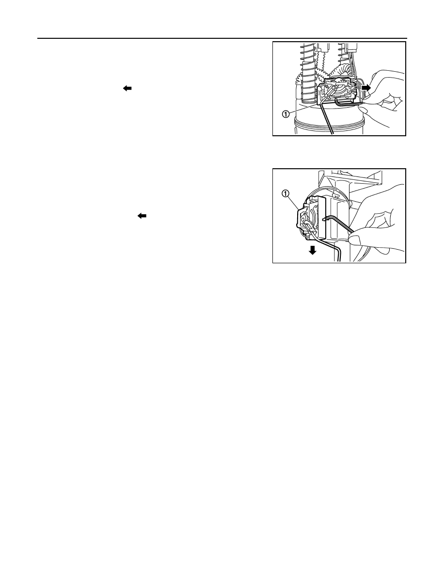
Push the pawl of fuel level sensor unit (1) mounting area with an
L-shaped iron rod or an equivalent to unlock.

CAUTION:

Be careful not to damage it.

b.

With the fuel level sensor unit unlocked, slide it in the direction
shown by the arrow (

).

Sub fuel level sensor unit assembly side

1.

Remove sub fuel level sensor unit according to the following procedure.

a.

Push the pawl of sub fuel level sensor unit (1) mounting area
with an L-shaped iron rod or an equivalent to unlock.

CAUTION:

Be careful not to damage it.

b.

With the sub fuel level sensor unit unlocked, slide it in the direc-
tion shown by the arrow (

).

ASSEMBLY

Install fuel level sensor unit and sub fuel level sensor unit according to the following procedure.
• Insert fuel level sensor unit and sub fuel level sensor unit all the way to the end until a “click” touch and

sound can be recognized.

• Pull fuel level sensor unit and sub fuel level sensor unit in the removal direction to ensure that they do not

become detached.

Inspection

INFOID:0000000008457787

INSPECTION AFTER INSTALLATION

Use the following procedure to check for fuel leakage.
1.

Turn ignition switch “ON” (with engine stopped), then check connections for leakage by applying fuel pres-
sure to fuel piping.

2.

Start engine and let it idle and check there are no fuel leakage at the fuel system connections.

PBIC4900J

PBIC4899J

Revision: 2012 September

2013 MURANO

FUEL TANK

FL-11

< REMOVAL AND INSTALLATION >

C

D

E

F

G

H

I

J

K

L

M

A

FL

N

P

O

FUEL TANK

Exploded View

INFOID:0000000008457788

Removal and Installation

INFOID:0000000008457789

WARNING:

Be sure to read “General Precautions” when working on the fuel system. Refer to 

FL-2, "General Pre-

cautions"

.

REMOVAL

• Drain fuel from fuel tank if necessary. Refer to 

FL-6, "Removal and Installation"

.

• Perform work on level place.

1.

Perform steps 2 to 7 of “REMOVAL” in “ FUEL LEVEL SENSOR UNIT, FUEL FILTER AND FUEL PUMP
ASSEMBLY” on main and sub fuel level sensor units. Refer to 

FL-6, "Removal and Installation"

.

2.

Remove center muffler. Refer to 

EX-5, "Exploded View"

.

3.

Remove propeller shaft. Refer to 

DLN-78, "Exploded View"

. (AWD models)

1.

Clamp

2.

EVAP/Vent line hose

3.

Fuel tank

4.

Fuel tank mounting band (RH)

5.

Fuel tank protector

6.

Fuel tank protector (RH)

7.

Fuel tank protector (LH)

8.

Fuel tank mounting band (LH)

9.

Clamp

10. Clamp

11.

Fuel filler hose

12. EVAP (Recirculation) hose

13. Clamp

14.

Fuel filler tube

15. Grommet

16. Fuel filler cap

: N·m (kg-m, ft-lb)

: N·m (kg-m, in-lb)

JPBIA5442GB

Revision: 2012 September

2013 MURANO

FL-12

< REMOVAL AND INSTALLATION >

FUEL TANK

4.

Remove parking rear brake cables. Refer to 

PB-6, "Exploded View"

.

5.

Remove rear suspension member assembly. Refer to 

RSU-18, "Exploded View"

. (AWD models)

NOTE:
For this service, drive shaft, final drive, and rear suspension member are required not to be separate one
another during removal.

6.

Remove fuel tank protectors.

7.

Disconnect fuel filler hose (1), EVAP/Vent line hose (3), and
EVAP (Recirculation) hose (2) from the side other than the fuel
tank side.

8.

Support the lower part of fuel tank (1) with transmission jack (A).

CAUTION:

Support the position that fuel tank mounting bands never
engage.

9.

Remove fuel tank mounting bands.

10. Supporting with hands, descend transmission jack carefully, and remove fuel tank.

CAUTION:

• Check that all connection points have been disconnected.
• Confirm there is no interference with vehicle.

11. Remove fuel filler tube if necessary.

INSTALLATION

Note the following, and install in the reverse order of removal.
• Surely clamp fuel hoses and insert hose to the length below.

• Be sure hose clamp is not placed on swelled area of fuel tube.
• Tighten the clamp hand with the top mark (A) until the mark is on

the bolt head flange.

• To connect quick connector, refer to 

FL-6, "Removal and Installation"

.

: Vehicle front

JPBIA1696ZZ

JPBIA0145ZZ

Fuel filler hose 

: 35 mm (1.38 in)

The other hoses

: 25 mm (0.98 in)

JPBIA0146ZZ

Revision: 2012 September

2013 MURANO

FUEL TANK

FL-13

< REMOVAL AND INSTALLATION >

C

D

E

F

G

H

I

J

K

L

M

A

FL

N

P

O

Inspection

INFOID:0000000008457790

INSPECTION AFTER INSTALLATION

Use the following procedure to check for fuel leakage.
1.

Turn ignition switch “ON” (with engine stopped), and check connections for leakage by applying fuel pres-
sure to fuel piping.

2.

Start engine and rev it up and check there are no fuel leakage at the fuel system tube and hose connec-
tions.

• After removing/installing rear suspension assembly, check to adjust wheel alignment and then, adjust neutral

position of steering angle sensor. Refer to 

RSU-6, "Inspection"

 and 

BRC-9, "ADJUSTMENT OF STEERING

ANGLE SENSOR NEUTRAL POSITION : Special Repair Requirement"

.

Revision: 2012 September

2013 MURANO

FL-14

< REMOVAL AND INSTALLATION >

EVAP CANISTER

EVAP CANISTER

Exploded View

INFOID:0000000008457791

Removal and Installation

INFOID:0000000008457792

REMOVAL

1.

Lift up the vehicle.

2.

Remove EVAP canister fixing bolt.

3.

Remove EVAP canister.

NOTE:
The EVAP canister vent control valve and EVAP canister system pressure sensor can be removed without
removing the EVAP canister.

INSTALLATION

CAUTION:

Do not reuse O-rings.
Install in the reverse order of removal.
NOTE:
Tighten EVAP canister fixing bolt to the specified torque.

DISASSEMBLY

1.

Turn EVAP canister vent control valve counterclockwise.

2.

Remove the EVAP canister vent control valve.

ASSEMBLY

Assemble in the reverse order of disassembly.

CAUTION:

Always replace O-ring with a new one.

PBIB1383E

PBIB1384E

Revision: 2012 September

2013 MURANO

EVAP CANISTER

FL-15

< REMOVAL AND INSTALLATION >

C

D

E

F

G

H

I

J

K

L

M

A

FL

N

P

O

Inspection

INFOID:0000000008457793

Check EVAP canister as per the following:

1.

Block port (B).

2.

Blow air into port (A) and check that it flows freely out of port (C).

3.

Release blocked port (B).

4.

Apply vacuum pressure to port (B) and check that vacuum pres-
sure exists at the ports (A) and (C). 

5.

Block port (A) and (B).

6.

Apply pressure to port (C) and check that there is no leakage.

JMBIA1133ZZ

Revision: 2012 September

2013 MURANO

FL-16

< SERVICE DATA AND SPECIFICATIONS (SDS) 

SERVICE DATA AND SPECIFICATIONS (SDS)

SERVICE DATA AND SPECIFICATIONS (SDS)

SERVICE DATA AND SPECIFICATIONS (SDS)

Fuel Tank

INFOID:0000000008457794

Standard and Limit

Fuel tank capacity

Approx. 82   (21-5/8 US gal, 18 Imp gal)

Fuel recommendation

Refer to 

GI-35

Revision: 2012 September

2013 MURANO

FSU-1

SUSPENSION

C

D

F

G

H

I

J

K

L

M

SECTION 

FSU

A

B

FSU

N

O

P

CONTENTS

FRONT SUSPENSION

SYMPTOM DIAGNOSIS  ...............................

2

NOISE, VIBRATION AND HARSHNESS 
(NVH) TROUBLESHOOTING  .............................

2

NVH Troubleshooting Chart  ......................................

2

PRECAUTION ...............................................

3

PRECAUTIONS ...................................................

3

FOR USA AND CANADA ............................................

3

FOR USA AND CANADA : Precaution for Supple-
mental Restraint System (SRS) "AIR BAG" and 
"SEAT BELT PRE-TENSIONER" ............................
..

3

FOR USA AND CANADA : Precaution for Proce-
dure without Cowl Top Cover ..................................
..

3

FOR USA AND CANADA : Precautions for Sus-
pension ....................................................................
..

3

FOR MEXICO  ..............................................................

4

FOR MEXICO : Precaution for Supplemental Re-
straint System (SRS) "AIR BAG" and "SEAT BELT 
PRE-TENSIONER" .................................................
..

4

FOR MEXICO : Precaution for Procedure without 
Cowl Top Cover  ......................................................
..

4

FOR MEXICO : Precautions for Suspension  ............

4

PREPARATION ............................................

5

PREPARATION ...................................................

5

Special Service Tool  .................................................

5

Commercial Service Tool  ..........................................

5

PERIODIC MAINTENANCE ..........................

6

FRONT SUSPENSION ASSEMBLY  ...................

6

Inspection ..................................................................

6

WHEEL ALIGNMENT  ........................................

7

Inspection .................................................................

7

Adjustment ................................................................

7

REMOVAL AND INSTALLATION  ................

9

FRONT COIL SPRING AND STRUT  .................

9

Exploded View ..........................................................

9

Removal and Installation  ..........................................

9

Disassembly and Assembly .....................................

10

Inspection ................................................................

11

Disposal ...................................................................

11

TRANSVERSE LINK .........................................

12

Exploded View .........................................................

12

Removal and Installation  .........................................

12

Inspection ................................................................

12

FRONT STABILIZER  ........................................

14

Exploded View .........................................................

14

Removal and Installation  .........................................

14

Inspection ................................................................

15

UNIT REMOVAL AND INSTALLATION ......

16

FRONT SUSPENSION MEMBER .....................

16

Exploded View .........................................................

16

Removal and Installation  .........................................

16

Inspection ................................................................

16

SERVICE DATA AND SPECIFICATIONS 
(SDS) ............................................................

18

SERVICE DATA AND SPECIFICATIONS 
(SDS) .................................................................

18

Wheel Alignment  .....................................................

18

Ball Joint  ..................................................................

19

Wheelarch Height  ....................................................

19

Revision: 2012 September

2013 MURANO

FSU-2

< SYMPTOM DIAGNOSIS >

NOISE, VIBRATION AND HARSHNESS (NVH) TROUBLESHOOTING

SYMPTOM DIAGNOSIS

NOISE, VIBRATION AND HARSHNESS (NVH) TROUBLESHOOTING

NVH Troubleshooting Chart

INFOID:0000000008459201

Use chart below to find the cause of the symptom. If necessary, repair or replace these parts.

×

: Applicable

Reference

FS

U-

9

FSU-12

FS

U-

1

4

FSU-1

6

FS

U-

1

1

FS

U-

1

1

FS

U-

9

FSU-12

FS

U-

1

4

FSU-1

6

FS

U-

7

FS

U-15

NVH in DLN

 section

NVH in DLN

 section

NVH in 

F

AX 

and FS

U sections

NVH in 

WT section

NVH in 

WT section

NVH in F

A

X section

NVH in BR 

section

NVH in ST 

section

Possible cause and SUSPECTED PARTS

Im

p

rop

er i

n

s

tal

la

tio

n

loo

s

ene

s

s

S

hoc

k

 ab

so

rbe

r d

e

fo

rma

tio

n,

 da

ma

ge

 o

r de

fle

c

tion

B

u

s

h

in

or m

o

u

n

ting

 d

e

te

rio

rati

o

n

P

a

rt

s interference

S

p

ri

ng

 fat

ig

u

e

S

us

pe

ns

ion

 lo

os

en

es

s

In

co

rrec

t wh

ee

l a

lig

nm

en

t

S

ta

b

iliz

er b

a

r f

a

ti

gu

e

PR

OP

EL

LE

R

 S

H

A

F

T

 (

A

W

D

)

DIFFERENTIAL (A

WD)

F

R

ONT

 AXLE AND FRONT S

U

SPENSION

TI

RE

ROAD  

 WHEEL

DRIV

E SHAFT

BR

AK

E

S

T

EERING

Symptom

FRONT SUSPENSION

Noise

×

×

×

×

×

×

×

×

×

×

×

×

×

×

Shake

×

×

×

×

×

×

×

×

×

×

×

×

Vibration

×

×

×

×

×

×

×

×

×

×

Shimmy

×

×

×

×

×

×

×

×

×

×

Judder 

×

×

×

×

×

×

×

×

Poor quality ride or 
handling

×

×

×

×

×

×

×

×

×

×

Revision: 2012 September

2013 MURANO

PRECAUTIONS

FSU-3

< PRECAUTION >

C

D

F

G

H

I

J

K

L

M

A

B

FSU

N

O

P

PRECAUTION

PRECAUTIONS

FOR USA AND CANADA

FOR USA AND CANADA : Precaution for Supplemental Restraint System (SRS) "AIR 
BAG" and "SEAT BELT PRE-TENSIONER"

INFOID:0000000008459202

The Supplemental Restraint System such as “AIR BAG” and “SEAT BELT PRE-TENSIONER”, used along
with a front seat belt, helps to reduce the risk or severity of injury to the driver and front passenger for certain
types of collision. This system includes seat belt switch inputs and dual stage front air bag modules. The SRS
system uses the seat belt switches to determine the front air bag deployment, and may only deploy one front
air bag, depending on the severity of a collision and whether the front occupants are belted or unbelted.
Information necessary to service the system safely is included in the “SRS AIR BAG” and “SEAT BELT” of this
Service Manual.

WARNING:

Always observe the following items for preventing accidental activation.
• To avoid rendering the SRS inoperative, which could increase the risk of personal injury or death in

the event of a collision that would result in air bag inflation, all maintenance must be performed by
an authorized NISSAN/INFINITI dealer.

• Improper maintenance, including incorrect removal and installation of the SRS, can lead to personal

injury caused by unintentional activation of the system. For removal of Spiral Cable and Air Bag
Module, see “SRS AIR BAG”.

• Never use electrical test equipment on any circuit related to the SRS unless instructed to in this Ser-

vice Manual. SRS wiring harnesses can be identified by yellow and/or orange harnesses or harness
connectors.

PRECAUTIONS WHEN USING POWER TOOLS (AIR OR ELECTRIC) AND HAMMERS

WARNING:

Always observe the following items for preventing accidental activation.
• When working near the Air Bag Diagnosis Sensor Unit or other Air Bag System sensors with the

ignition ON or engine running, never use air or electric power tools or strike near the sensor(s) with
a hammer. Heavy vibration could activate the sensor(s) and deploy the air bag(s), possibly causing
serious injury.

• When using air or electric power tools or hammers, always switch the ignition OFF, disconnect the

battery, and wait at least 3 minutes before performing any service.

FOR USA AND CANADA : Precaution for Procedure without Cowl Top Cover

INFOID:0000000008459203

When performing the procedure after removing cowl top cover, cover
the lower end of windshield with urethane, etc to prevent damage to
windshield.

FOR USA AND CANADA : Precautions for Suspension

INFOID:0000000008459204

• When installing rubber bushings, the final tightening must be carried out under unladen conditions with tires

on ground. Spilled oil might shorten the life of rubber bushings. Be sure to wipe off any spilled oil.

- Unladen conditions mean that fuel, engine coolant and lubricant are full. Spare tire, jack, hand tools and

mats are in designated positions.

• After servicing suspension parts, be sure to check wheel alignment.
• Self-lock nuts are not reusable. Always use new ones when installing. Since new self-lock nuts are pre-oiled,

tighten as they are. 

PIIB3706J

Revision: 2012 September

2013 MURANO

FSU-4

< PRECAUTION >

PRECAUTIONS

FOR MEXICO

FOR MEXICO : Precaution for Supplemental Restraint System (SRS) "AIR BAG" and 
"SEAT BELT PRE-TENSIONER"

INFOID:0000000008459205

The Supplemental Restraint System such as “AIR BAG” and “SEAT BELT PRE-TENSIONER”, used along
with a front seat belt, helps to reduce the risk or severity of injury to the driver and front passenger for certain
types of collision. Information necessary to service the system safely is included in the “SRS AIR BAG” and
“SEAT BELT” of this Service Manual.

WARNING:

Always observe the following items for preventing accidental activation.
• To avoid rendering the SRS inoperative, which could increase the risk of personal injury or death in

the event of a collision that would result in air bag inflation, all maintenance must be performed by
an authorized NISSAN/INFINITI dealer.

• Improper maintenance, including incorrect removal and installation of the SRS, can lead to personal

injury caused by unintentional activation of the system. For removal of Spiral Cable and Air Bag
Module, see “SRS AIR BAG”.

• Never use electrical test equipment on any circuit related to the SRS unless instructed to in this Ser-

vice Manual. SRS wiring harnesses can be identified by yellow and/or orange harnesses or harness
connectors.

PRECAUTIONS WHEN USING POWER TOOLS (AIR OR ELECTRIC) AND HAMMERS

WARNING:

Always observe the following items for preventing accidental activation.
• When working near the Air Bag Diagnosis Sensor Unit or other Air Bag System sensors with the

ignition ON or engine running, never use air or electric power tools or strike near the sensor(s) with
a hammer. Heavy vibration could activate the sensor(s) and deploy the air bag(s), possibly causing
serious injury.

• When using air or electric power tools or hammers, always switch the ignition OFF, disconnect the

battery, and wait at least 3 minutes before performing any service.

FOR MEXICO : Precaution for Procedure without Cowl Top Cover

INFOID:0000000008459206

When performing the procedure after removing cowl top cover, cover
the lower end of windshield with urethane, etc to prevent damage to
windshield.

FOR MEXICO : Precautions for Suspension

INFOID:0000000008459207

• When installing rubber bushings, the final tightening must be carried out under unladen conditions with tires

on ground. Spilled oil might shorten the life of rubber bushings. Be sure to wipe off any spilled oil.

- Unladen conditions mean that fuel, engine coolant and lubricant are full. Spare tire, jack, hand tools and

mats are in designated positions.

• After servicing suspension parts, be sure to check wheel alignment.
• Self-lock nuts are not reusable. Always use new ones when installing. Since new self-lock nuts are pre-oiled,

tighten as they are. 

PIIB3706J

Revision: 2012 September

2013 MURANO

PREPARATION

FSU-5

< PREPARATION >

C

D

F

G

H

I

J

K

L

M

A

B

FSU

N

O

P

PREPARATION

PREPARATION

Special Service Tool

INFOID:0000000008459208

The actual shapes of Kent-More tools may differ from those of special service tools illustrated here.

Commercial Service Tool

INFOID:0000000008459209

Tool number
(Kent-More No.)
Tool name

Description

ST35652000
(

)

Strut attachment

Disassembling and assembling strut 

ZZA0807D

Tool name

Description

Spring compressor

Removing and installing coil spring

Power tool

Loosening bolts and nuts

S-NT717

PBIC0190E

Revision: 2012 September

2013 MURANO

FSU-6

< PERIODIC MAINTENANCE >

FRONT SUSPENSION ASSEMBLY

PERIODIC MAINTENANCE

FRONT SUSPENSION ASSEMBLY

Inspection

INFOID:0000000008459210

COMPONENT PART

Check the mounting conditions (looseness, backlash) of each component and component conditions (wear,
damage) are normal.

Ball Joint Axial End Play

1.

Set front wheels in a straight-ahead position.

2.

Move axle side of transverse link in the axial direction by hand.
Check there is no end play. 

CAUTION:

• Never depress brake pedal when measuring.
• Never perform with tires on level ground.
• Be careful not to damage ball joint boot. Never damage

the installation position by applying excessive force.

STRUT ASSEMBLY

Check for oil leakage, damage, and replace if necessary.

Axial end play

: Refer to 

FSU-19, "Ball Joint"

.

JSEIA0444ZZ

Revision: 2012 September

2013 MURANO

WHEEL ALIGNMENT

FSU-7

< PERIODIC MAINTENANCE >

C

D

F

G

H

I

J

K

L

M

A

B

FSU

N

O

P

WHEEL ALIGNMENT

Inspection

INFOID:0000000008459211

DESCRIPTION

CAUTION:

• Camber, caster, kingpin inclination angles cannot be adjusted.
• If camber, caster, or kingpin inclination angle is outside the standard, check front suspension parts

for wear and damage. Replace suspect parts if a malfunction is detected.

• Kingpin inclination angle is reference value, no inspection is required.
Measure wheel alignment under unladen conditions. 
NOTE:
“Unladen conditions” means that fuel, engine coolant, and lubricant are full. Spare tire, jack, hand tools and
mats are in designated positions.

PRELIMINARY CHECK

Check the following:
• Tires for improper air pressure and wear. Refer to 

WT-49, "Tire Air Pressure"

.

• Road wheels for runout.
• Wheel bearing axial end play. Refer to 

FAX-8, "Inspection"

 (2WD), 

FAX-34, "Inspection"

 (AWD).

• Transverse link ball joint axial end play. Refer to 

FSU-6, "Inspection"

.

• Strut operation.
• Each mounting part of axle and suspension for looseness and deformation.
• Each of suspension member, shock absorber, upper link and transverse link for cracks, deformation and

other damage.

• Vehicle height (posture).

GENERAL INFORMATION AND RECOMMENDATIONS

• A four-wheel thrust alignment should be performed.
- This type of alignment is recommended for any NISSAN/INFINITI vehicle.
- The four-wheel “thrust” process helps ensure that the vehicle is properly aligned and the steering wheel is

centered.

- The alignment rack itself should be capable of accepting any NISSAN/INFINITI vehicle.
- The rack should be checked to ensure that it is level.
• Make sure the machine is properly calibrated.
- Your alignment equipment should be regularly calibrated in order to give correct information.
- Check with the manufacturer of your specific equipment for their recommended Service/Calibration Sched-

ule.

ALIGNMENT PROCESS

IMPORTANT:
Use only the alignment specifications listed in this Service Manual.
• When displaying the alignment settings, many alignment machines use “indicators”: (Green/red, plus or

minus, Go/No Go). Never use these indicators.

- The alignment specifications programmed into your machine that operate these indicators may not be cor-

rect.

- This may result in an ERROR.
• Most camera-type alignment machines are equipped with both “Rolling Compensation” method and optional

“Jacking Compensation” method to “compensate” the alignment targets or head units. “Rolling Compensa-
tion” is the preferred method.

- If using the “Rolling Compensation” method, after installing the alignment targets or head units, push or pull

on the rear wheel to move the vehicle. Do not push or pull on the vehicle body.

- If using the “Jacking Compensation” method, after installing the alignment targets or head units, raise the

vehicle and rotate the wheels 1/2 turn both ways.
NOTE:
Do not use the “Rolling Compensation” method if you are using sensor-type alignment equipment.

- Follow all instructions for the alignment machine you're using for more information.

Adjustment

INFOID:0000000008459212

TOE-IN

Revision: 2012 September

2013 MURANO

FSU-8

< PERIODIC MAINTENANCE >

WHEEL ALIGNMENT

• Loosen the steering outer socket, and then adjust the length using steering inner socket. 

CAUTION:

• Always evenly adjust both toe-in alternately and adjust the difference between the left and right to

the standard. 

• Always fix the steering inner socket when tightening the steering outer socket. 

• After toe-in adjustment, adjust neutral position of steering angle sensor. Refer to 

BRC-9, "ADJUSTMENT OF

STEERING ANGLE SENSOR NEUTRAL POSITION : Special Repair Requirement"

.

Toe-in

: Refer to 

FSU-18, "Wheel Alignment"

.

Revision: 2012 September

2013 MURANO

FRONT COIL SPRING AND STRUT

FSU-9

< REMOVAL AND INSTALLATION >

C

D

F

G

H

I

J

K

L

M

A

B

FSU

N

O

P

REMOVAL AND INSTALLATION

FRONT COIL SPRING AND STRUT

Exploded View

INFOID:0000000008459213

Removal and Installation

INFOID:0000000008459214

REMOVAL

1.

Remove tires with power tool.

2.

Remove lock plate. Refer to 

BR-21, "FRONT : Exploded View"

.

3.

Remove wheel sensor. Refer to 

BRC-121, "FRONT WHEEL SENSOR : Exploded View"

.

4.

Remove stabilizer connecting rod from strut assembly. Refer to 

FSU-14, "Exploded View"

.

5.

Remove strut assembly from steering knuckle.

6.

Remove cowl top cover. Refer to 

EXT-20, "Exploded View"

.

7.

Remove mounting bolts of strut mounting insulator with power tool, and then remove strut assembly.

INSTALLATION

Note the following, and install in the reverse order of removal.
• Become it in projection (A) an illustration to the body outside.

• Perform final tightening of bolts and nuts, under unladen conditions

with tires on level ground.

1.

Piston rod lock nut

2.

Strut mounting insulator

3.

Strut mounting bearing

4.

Coil spring

5.

Bound bumper

6.

 Lower rubber seat

7.

Strut

Refer to 

GI-4, "Components"

 for symbols in the figure.

JPEIA0136GB

: Vehicle front

JPEIA0094ZZ

Revision: 2012 September

2013 MURANO


Content      ..     28      29      30      31     ..