Nissan Murano Z51 (2013 year). Manual - part 29


  Index      Manuals     Nissan Murano Z51 (2013 year) - Service and Repair Manual


Search            copyright infringement  


Content      ..     27      28      29      30     ..


Nissan Murano Z51 (2013 year). Manual - part 29


FRONT DRIVE SHAFT

FAX-47

< REMOVAL AND INSTALLATION >

[AWD]

C

E

F

G

H

I

J

K

L

M

A

B

FAX

N

O

P

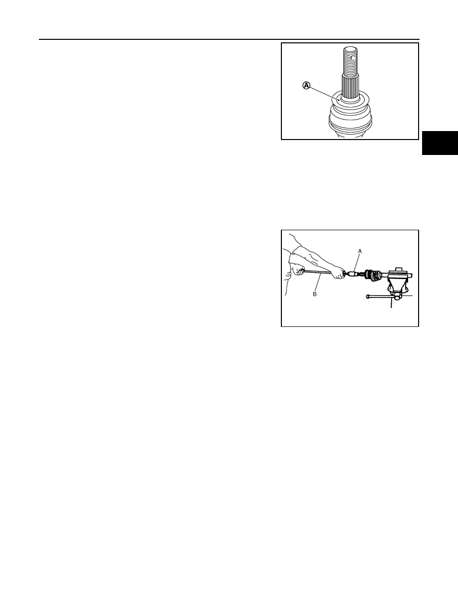
Apply paste [service parts (440037S000)] to cover entire flat
surface (A) of joint sub-assembly of drive shaft.

• Never use a power tool to tighten the wheel hub lock nut.
• Perform the final tightening of each of parts under unladen condi-

tions, which were removed when removing wheel hub and bearing
assembly and axle housing. 

• Never reuse cotter pin.

WHEEL SIDE

WHEEL SIDE : Disassembly and Assembly

INFOID:0000000008456088

DISASSEMBLY

1.

Fix shaft with a vise.

CAUTION:

Protect shaft using aluminum or copper plates when fixing with a vise.

2.

Remove boot bands, and then remove boot from joint sub-assembly.

3.

Screw drive shaft puller (A) into joint sub-assembly screw part to
a length of 30 mm (1.18 in) or more. Support drive shaft with one
hand and pull out joint sub-assembly with a sliding hammer (B)
from housing assembly.

CAUTION:

• Align a sliding hammer and drive shaft and remove them

by pulling firmly and uniformly.

• If joint sub-assembly cannot be pulled out, try after

removing drive shaft from vehicle.

4.

Remove circular clip (1) from housing assembly.

5.

Remove boot from housing assembly.

ASSEMBLY

1.

Clean the old grease on joint sub-assembly with paper waste.

2.

Fill serration slot joint sub-assembly with NISSAN genuine grease or equivalent until the serration slot and
ball groove become full to the brim.

CAUTION:

After applying grease, use a paper waste to wipe off old grease that has oozed out.

3.

 Install boot and boot bands to housing assembly.

CAUTION:

• Wrap serration on housing assembly with tape to protect the boot from damage.
• Never reuse boot and boot band.

4.

Remove the tape wrapped around the serration on housing assembly.

5.

Position the circular clip on groove at the housing assembly edge.

CAUTION:

Never reuse circular clip.
NOTE:
Drive joint inserter is recommended when installing circular clip.

6.

Align both center axles of the housing assembly edge and joint sub-assembly. Then assemble housing
assembly with circular clip joint sub-assembly.

Amount paste

: 1.0 – 3.0 g (0.04 – 0.10 oz)

JPDIG0122ZZ

JPDIF0015ZZ

Revision: 2012 September

2013 MURANO

FAX-48

< REMOVAL AND INSTALLATION >

[AWD]

FRONT DRIVE SHAFT

7.

Install joint sub-assembly to housing assembly using plastic
hammer.

CAUTION:

Confirm that joint sub-assembly is correctly engaged while
rotating drive housing assembly.

8.

Apply the specified amount of grease into the boot inside from
large diameter side of boot.

9.

Install the boot securely into grooves (indicated by “*” marks)
shown in the figure.

CAUTION:

If grease adheres to the boot mounting surface (indicated
by “*” mark) on the housing assembly or joint sub-assem-
bly, boot may be removed. Remove all grease from the boot
mounting surface.

10. To prevent the deformation of the boot, adjust the boot installa-

tion length (L) to the specified value shown below by inserting
the suitable tool into inside of the boot from the large diameter
side of the boot and discharging the inside air.

CAUTION:

• If the boot installation length exceeds the standard, it may cause breakage of boot.
• Be careful not to touch the inside of the boot with a tip of tool.

11. Secure the large and small ends of the boot with boot bands

using the boot band crimping tool (A) [SST: KV40107300 (

)].

CAUTION:

Never reuse boot band.

NOTE:
Secure boot band so that dimension (A) meets the specification
as shown in the figure.

12. Secure joint sub-assembly and housing assembly, and then

make sure that they are in the correct position when rotating
boot. Reinstall them using boot bands when boot installation
positions become incorrect.

CAUTION:

Never reuse boot band.

TRANSAXLE SIDE

TRANSAXLE SIDE : Disassembly and Assembly

INFOID:0000000008456089

DISASSEMBLY

Grease amount

: Refer to 

FAX-53, "Drive Shaft"

.

RAC0049D

L

: Refer to 

FAX-53, "Drive Shaft"

.

JPDIF0222ZZ

JPDIF0012ZZ

A

: 7.0 mm (0.276 in) or less

JPDIF0268ZZ

Revision: 2012 September

2013 MURANO

FRONT DRIVE SHAFT

FAX-49

< REMOVAL AND INSTALLATION >

[AWD]

C

E

F

G

H

I

J

K

L

M

A

B

FAX

N

O

P

Left Side

1.

Fix drive shaft with a vise.

CAUTION:

Protect shaft using aluminum or copper plates when fixing with a vise.

2.

Disassemble boot (wheel side). Refer to 

FAX-47, "WHEEL SIDE : Disassembly and Assembly"

.

3.

Remove boot bands and boot (transaxle side).

Right Side

1.

Fix drive shaft with a vise.

CAUTION:

Protect shaft using aluminum or copper plates when fixing with a vise.

2.

Disassemble boot (wheel side). Refer to 

FAX-47, "WHEEL SIDE : Disassembly and Assembly"

.

3.

Remove dynamic damper, follow the procedure described below. 

a.

Remove damper bands.

b.

Remove dynamic damper from shaft.

4.

Remove boot bands and boot (transaxle side).

5.

Remove dust shield from housing assembly.

6.

Remove support bearing from link shaft, follow the procedure described below.

a.

Press out bearing housing and support bearing from link shaft.

b.

Remove dust shield from bearing housing.

c.

Remove snap ring (1).

d.

Remove oil seal.

e.

Press out support bearing from bearing housing (1) with drift (A)
[SST: ST17130000 (

)]

ASSEMBLY

Left Side

1.

Install dust shield.

CAUTION:

Never reuse dust shield.

2.

Install circular clip.

CAUTION:

Never reuse circular clip.

3.

Clean old grease on housing assembly with paper waste.

JPDIF0177ZZ

JPDIF0192ZZ

Revision: 2012 September

2013 MURANO

FAX-50

< REMOVAL AND INSTALLATION >

[AWD]

FRONT DRIVE SHAFT

4.

Install boot securely into grooves (indicated by “*” marks) shown
in the figure.

CAUTION:

If grease adheres to the boot mounting surface (indicated
by “*” mark) on housing assembly, boot may be removed.
Remove all grease from the boot mounting surface.

5.

To prevent the deformation of the boot, adjust the boot installa-
tion length (L) to the specified value shown below by inserting
the suitable tool into the inside of boot from the large diameter
side of boot and discharging inside air.

CAUTION:

• If the boot installation length exceeds the standard, it may cause breakage of boot.
• Be careful not to touch the inside of the boot with the tip of tool.

6.

Install boot bands securely as shown in the figure.

a.

Put boot band in the groove on drive shaft boot. Then fit pawls
(

) into holes to temporary installation.

NOTE:
For the large diameter side, fit projection (A) and guide slit (B) at
first.

b.

Pinch projection on the band with suitable pliers to tighten band.

c.

Insert tip of band below end of the pawl.

7.

Secure housing assembly, and then make sure that they are in
the correct position when rotating boot. Reinstall them with boot
bands when the mounting positions become incorrect.

Right Side

1.

Install support bearing from link shaft, follow the procedure described below.

a.

Press support bearing to bearing housing (1) with drift (A) [SST:
ST35271000 (

)]

L

:  Refer  to 

FAX-53, "Drive Shaft"

.

JPDIF0144ZZ

JPDIF0157ZZ

JPDIF0158ZZ

JPDIF0192ZZ

Revision: 2012 September

2013 MURANO

FRONT DRIVE SHAFT

FAX-51

< REMOVAL AND INSTALLATION >

[AWD]

C

E

F

G

H

I

J

K

L

M

A

B

FAX

N

O

P

b.

Install snap ring (1).

CAUTION:

Never reuse snap ring.

c.

Install dust shield to baring housing.

CAUTION:

Never reuse dust shield.

d.

Install oil seal to bearing housing with drift.

CAUTION:

• Never reuse oil seal.
• Apply multi - purpose grease to oil seal lip.

e.

Press bearing housing assembly to link shaft.

f.

Install circular clip to link shaft.

CAUTION:

Never reuse circular clip.

2.

Clean old grease on housing assembly with paper waste.

3.

Install boot securely into grooves (indicated by “*” marks) shown
in the figure.

CAUTION:

If grease adheres to the boot mounting surface (indicated
by “*” mark) on housing assembly, boot may be removed.
Remove all grease from the boot mounting surface.

4.

To prevent the deformation of the boot, adjust the boot installa-
tion length (L) to the specified value shown below by inserting
the suitable tool into the inside of boot from the large diameter
side of boot and discharging inside air.

CAUTION:

• If the boot installation length exceeds the standard, it may cause breakage of boot.
• Be careful not to touch the inside of the boot with the tip of tool.

5.

Install boot bands securely as shown in the figure.

a.

Put boot band in the groove on drive shaft boot. Then fit pawls
(

) into holes to temporary installation.

NOTE:
For the large diameter side, fit projection (A) and guide slit (B) at
first.

b.

Pinch projection on the band with suitable pliers to tighten band.

c.

Insert tip of band below end of the pawl.

6.

Secure housing assembly, and then make sure that they are in
the correct position when rotating boot. Reinstall them with boot
bands when the mounting positions become incorrect.

7.

Assemble boot (wheel side) and joint sub-assembly. Refer to

FAX-47, "WHEEL SIDE : Disassembly and Assembly"

.

8.

Install dynamic damper, follow the procedure described below. 

a.

Install dynamic damper to shaft.

L

: Refer to 

FAX-52, "Inspection"

.

JPDIF0177ZZ

JPDIF0144ZZ

JPDIF0157ZZ

JPDIF0158ZZ

Revision: 2012 September

2013 MURANO

FAX-52

< REMOVAL AND INSTALLATION >

[AWD]

FRONT DRIVE SHAFT

b.

Secure dynamic damper with bands in the following specified
position (A) when installing.

CAUTION:

Never reuse bands.

Inspection

INFOID:0000000008456090

INSPECTION AFTER REMOVAL

• Move joint up/down, left/right, and in the axial directions. Check for motion that is not smooth and for signifi-

cant looseness.

• Check boot for cracks, damage, and leakage of grease.
• Disassemble drive shaft and exchange malfunctioning part if there

is a non-standard condition.

INSPECTION AFTER DISASSEMBLY

Shaft

Check shaft for runout, cracks, or other damage. Replace if necessary.

Dynamic Damper

Check damper for cracks or wear. Replace if necessary.

Joint Sub-Assembly (Wheel Side)

Check the following:
• Joint sub-assembly for rough rotation and excessive axial looseness.
• The inside of the joint sub-assembly for entry of foreign material.
• Joint sub-assembly for compression scars, cracks, and fractures inside of joint sub-assembly.
Replace joint sub-assembly if there are any non-standard conditions of components.

Housing Assembly (Transaxle Side)

Replace housing assembly if there is scratching or wear of housing assembly roller contact surface.

Link Shaft (Right side)

Check shaft for runout, cracks, or other damage. Replace if necessary.

Support Bearing (Right Side)

Make sure wheel bearing rolls freely and is free from noise, cracks, pitting or wear. Replace support bearing if
there are any non-standard conditions.

Support Bearing Bracket (Right Side)

Check for bending, cracks, or damage. Replace support bearing bracket if there are any non-standard condi-
tions.

: Refer to 

FAX-53, "Drive Shaft"

.

JPDIF0178ZZ

SDIA1190J

Revision: 2012 September

2013 MURANO

SERVICE DATA AND SPECIFICATIONS (SDS)

FAX-53

< SERVICE DATA AND SPECIFICATIONS (SDS) 

[AWD]

C

E

F

G

H

I

J

K

L

M

A

B

FAX

N

O

P

SERVICE DATA AND SPECIFICATIONS (SDS)

SERVICE DATA AND SPECIFICATIONS (SDS)

Wheel Bearing

INFOID:0000000008456091

Drive Shaft

INFOID:0000000008456092

Item

Standard

Axial end play

0.05 mm (0.002 in) or less

Item

Standard

Left side

Right side

Grease quantity

Wheel side

170 – 190 g (6.00 – 6.70 oz)

Transaxle side

155 – 175 g (5.47 – 6.17 oz)

Boots installed length

Wheel side

158.6 mm (6.24 in)

Transaxle side

163.67 mm (6.44 in)

159.47 mm (6.28 in)

Dimension of dynamic damper

202 – 208 mm (7.95 – 8.19 in)

Revision: 2012 September

2013 MURANO

FL-1

ENGINE

C

D

E

F

G

H

I

J

K

L

M

SECTION 

FL

A

FL

N

O

P

CONTENTS

FUEL SYSTEM

PRECAUTION ...............................................

2

PRECAUTIONS ...................................................

2

General Precautions  .................................................

2

PREPARATION ............................................

3

PREPARATION ...................................................

3

Special Service Tool  .................................................

3

Commercial Service Tool  ..........................................

3

PERIODIC MAINTENANCE ..........................

4

FUEL SYSTEM  ....................................................

4

Inspection ..................................................................

4

Quick Connector  .......................................................

4

REMOVAL AND INSTALLATION ................

5

FUEL LEVEL SENSOR UNIT, FUEL FILTER 
AND FUEL PUMP ASSEMBLY  ..........................

5

Exploded View  ..........................................................

5

Removal and Installation  ..........................................

6

Disassembly and Assembly ......................................

9

Inspection ................................................................

10

FUEL TANK  ......................................................

11

Exploded View .........................................................

11

Removal and Installation  .........................................

11

Inspection ................................................................

13

EVAP CANISTER ..............................................

14

Exploded View .........................................................

14

Removal and Installation  .........................................

14

Inspection ................................................................

15

SERVICE DATA AND SPECIFICATIONS 
(SDS) ............................................................

16

SERVICE DATA AND SPECIFICATIONS 
(SDS) .................................................................

16

Fuel Tank .................................................................

16

Revision: 2012 September

2013 MURANO

FL-2

< PRECAUTION >

PRECAUTIONS

PRECAUTION

PRECAUTIONS

General Precautions

INFOID:0000000008457779

WARNING:

When replacing fuel line parts, be sure to observe the following.
• Put a “CAUTION: FLAMMABLE” sign in the workshop.
• Be sure to work in a well ventilated area and furnish workshop with a CO

2

 fire extinguisher. 

• Never smoke while servicing fuel system. Keep open flames and sparks away from the work area.

CAUTION:

• Use gasoline required by the regulations for octane number. Refer to 

GI-35, "Fuel"

.

• Before removing fuel line parts, perform out the following procedures:
- Put drained fuel in an explosion-proof container and put the lid on securely. Keep the container in

safe area.

- Release fuel pressure from the fuel lines. Refer to 

EC-517, "Inspection"

.

- Disconnect the battery cable from the negative terminal. 
• Always replace O-ring and clamps with new ones.
• Never kink or twist tubes when they are being installed.
• Never tighten hose clamps excessively to avoid damaging hoses. 
• After installing tubes, check there is no fuel leakage at connections in the following steps.
- Apply fuel pressure to fuel lines with turning ignition switch “ON” (with engine stopped). Then check

for fuel leakage at connections.

- Start engine and rev it up and check for fuel leakage at connections.
• Use only a genuine NISSAN fuel filler cap as a replacement. If an incorrect fuel filler cap is used, the

“MIL” may come on.

• For servicing “On Board Refueling Vapor Recovery (ORVR)” parts, refer to 

EC-457, "Description"

.

Revision: 2012 September

2013 MURANO

PREPARATION

FL-3

< PREPARATION >

C

D

E

F

G

H

I

J

K

L

M

A

FL

N

P

O

PREPARATION

PREPARATION

Special Service Tool

INFOID:0000000008457780

The actual shapes of Kent-Moore tools may differ from those of special service tools illustrated here.

Commercial Service Tool

INFOID:0000000008457781

(Kent-Moore No.)
Tool name

Description

(J-46211)
Fuel tank lock ring wrench

Removing and installing fuel tank retainer

SBIA0388E

Tool name

Description

Power tool

Loosening nuts and bolts

PBIC0190E

Revision: 2012 September

2013 MURANO

FL-4

< PERIODIC MAINTENANCE >

FUEL SYSTEM

PERIODIC MAINTENANCE

FUEL SYSTEM

Inspection

INFOID:0000000008457782

Inspect fuel lines, fuel filler cap, and fuel tank for improper attach-
ment, leakage, cracks, damage, loose connections, chafing or dete-
rioration.

If necessary, repair or replace damaged parts.

Quick Connector

INFOID:0000000008457783

CAUTION:

• After connecting fuel tube quick connectors, check quick con-

nectors are secure.

• Ensure that connector and resin tube never contact any adja-

cent parts.

A

: Engine

B

: Fuel line

C

:  Fuel  tank

JPBIA0129ZZ

1

: Quick connector

2

:  Retainer

A

: Hard tube (or the equivalent)

B

: Connection (cross-section)

C

: Resin tube

D

: To under floor fuel line

E

: To fuel tank

F

:  Tab

G

: Disconnection

JPBIA0130ZZ

Revision: 2012 September

2013 MURANO

FUEL LEVEL SENSOR UNIT, FUEL FILTER AND FUEL PUMP ASSEMBLY

FL-5

< REMOVAL AND INSTALLATION >

C

D

E

F

G

H

I

J

K

L

M

A

FL

N

P

O

REMOVAL AND INSTALLATION

FUEL LEVEL SENSOR UNIT, FUEL FILTER AND FUEL PUMP ASSEMBLY

Exploded View

INFOID:0000000008457784

REMOVAL

DISASSEMBLY

1.

Retainer

2.

Sub fuel level sensor unit

3.

Seal packing

4.

Main fuel level sensor unit, fuel filter 
and fuel pump assembly

A.

Right side

B.

Left side

: Vehicle front

: Always replace after every disassembly.

JPBIA1694GB

Revision: 2012 September

2013 MURANO

FL-6

< REMOVAL AND INSTALLATION >

FUEL LEVEL SENSOR UNIT, FUEL FILTER AND FUEL PUMP ASSEMBLY

Removal and Installation

INFOID:0000000008457785

WARNING:

Read “General Precautions” when working on the fuel system. Refer to 

FL-2, "General Precautions"

.

REMOVAL

1.

Check fuel level on a level ground. If the fuel level is 7/8 of the fuel tank (full or nearly full), draw appropri-
ate amount of fuel from the fuel tank.

• In the event of malfunction in fuel pump, insert a hose measuring 25mm (0.98 in) in diameter into the

filler opening to draw approximately 20 liters (5-1/4 US gal,4-3/8 Imp gal) fuel.

2.

Release the fuel pressure from the fuel lines. Refer to 

EC-517, "Inspection"

.

3.

Open fuel filler lid.

4.

Open filler cap and release the pressure inside fuel tank.

5.

Remove rear seat cushion and reclining device assembly. Refer to 

SE-82, "Exploded View"

.

6.

Peel off floor carpet, then remove inspection hole cover units by
turning clips clockwise by 90 degrees.

1.

Sub fuel level sensor unit

2.

Sub fuel level sensor unit base

3.

Fuel filter and fuel pump assembly

4.

Fuel level sensor unit

: Vehicle front

PBIC4901J

Guideline:

Draw approximately 20 liters (5-1/4 US gal) from a full-tank condition.

Left side

: Main fuel level sensor unit, fuel filter 
and fuel pump assembly

Right side

: Sub fuel level sensor unit

SBIA0479E

Revision: 2012 September

2013 MURANO

FUEL LEVEL SENSOR UNIT, FUEL FILTER AND FUEL PUMP ASSEMBLY

FL-7

< REMOVAL AND INSTALLATION >

C

D

E

F

G

H

I

J

K

L

M

A

FL

N

P

O

7.

Disconnect harness connector, fuel feed tube and EVAP hose.

Disconnect quick connector as follows:

• Hold the sides of connector, push in tabs (B) and pull out fuel

feed tube.

• If quick connector sticks to tube of main fuel level sensor unit,

push and pull quick connector several times until they start to
move. Then disconnect them by pulling.

CAUTION:

• Quick connector (1) can be disconnected when the tabs

(F) are completely depressed. Never twist it more than
necessary.

• Never use any tools to disconnected quick connector.
• Keep resin tube (C) away from heat. Be especially careful

when welding near the resin tube.

• Prevent acid liquid such as battery electrolyte, etc. from

getting on resin tube.

• Never bend or twist resin tube during installation and dis-

connection. 

• Never remove the remaining retainer (2) on hard tube (or

the equivalent) (A) except when resin tube or retainer is
replaced.

• When resin tube or hard tube (or the equivalent) is

replaced, also replace retainer with new one. 

PBIC1807E

A

:  Pull

JPBIA0134ZZ

B

: Connection (cross-section)

D

: To under floor fuel line

E

: To fuel tank

G

: Disconnection

Retainer color: Green

JPBIA0130ZZ

Revision: 2012 September

2013 MURANO

FL-8

< REMOVAL AND INSTALLATION >

FUEL LEVEL SENSOR UNIT, FUEL FILTER AND FUEL PUMP ASSEMBLY

• To keep the connecting portion clean and to avoid dam-

age and foreign materials, cover them completely with
plastic bags (A) or something similar.      

8.

Remove retainer for main fuel level sensor unit, fuel filter and
fuel pump assembly and sub fuel level sensor unit with fuel tank
lock ring wrench (SST) by turning counterclockwise.

9.

Remove main fuel level sensor unit, fuel filter and fuel pump assembly, and sub fuel level sensor unit.
• Raise main fuel level sensor unit, fuel filter and fuel pump

assembly, and disconnect fuel hose connector (push in tabs
and pull out) and sub fuel level sensor unit harness connector.

• Raise and release sub fuel level sensor unit to remove.

INSTALLATION

Note to the following, and install in the reverse order of removal.

Main and Sub Fuel Level Sensor Unit

1.

Install new seal packing to fuel tank without any twist.

2.

Connect fuel hose connector (push in until it stops) and sub fuel
level sensor unit harness connector.
NOTE:
When installing fuel hose connector insert them fully until a click
sound of full stopper engagement is heard.

JPBIA0135ZZ

SBIA0411E

SBIA0396E

SBIA0398E

Revision: 2012 September

2013 MURANO

FUEL LEVEL SENSOR UNIT, FUEL FILTER AND FUEL PUMP ASSEMBLY

FL-9

< REMOVAL AND INSTALLATION >

C

D

E

F

G

H

I

J

K

L

M

A

FL

N

P

O

3.

Align the direction mark on main fuel level sensor unit, fuel filter
and fuel pump assembly and sub fuel level sensor unit with that
on fuel tank as shown in the figure, and install them to fuel tank.

CAUTION:

• Never allow seal packing to drop.
• Never bend float arm during installing.

4.

Install retainer for main fuel level sensor unit, fuel filter and fuel
pump assembly and sub fuel level sensor unit with fuel tank lock
ring wrench (SST) by turning clockwise.

CAUTION:

Install retainer horizontally.

Quick Connector

Connect quick connector as follows:

1.

Check the connection for damage or any foreign materials.

2.

Align the connector with the tube, then insert the connector straight into the tube until a click sound is
heard.

3.

After connecting, check that the connection is secure by following method.
• Pull (A) the tube and the connector to check they are securely

connected.

• Visually confirm that the two retainer tabs are connected to the

connector.

Disassembly and Assembly

INFOID:0000000008457786

DISASSEMBLY

Fuel level sensor unit, fuel filter and fuel pump assembly side

1.

Disconnect harness connector.

2.

Remove fuel level sensor unit according to the following procedure.

SBIA0397E

SBIA0411E

JPBIA0140ZZ

Revision: 2012 September

2013 MURANO


Content      ..     27      28      29      30     ..