Nissan Murano Z51 (2012 year). Manual - part 88


  Index      Manuals     Nissan Murano Z51 (2012 year) - Service and Repair Manual


Search            copyright infringement  


Content      ..     86      87      88      89     ..


Nissan Murano Z51 (2012 year). Manual - part 88


ST-94

< REMOVAL AND INSTALLATION >

[WITHOUT HEATED STEERING WHEEL]

STEERING GEAR AND LINKAGE

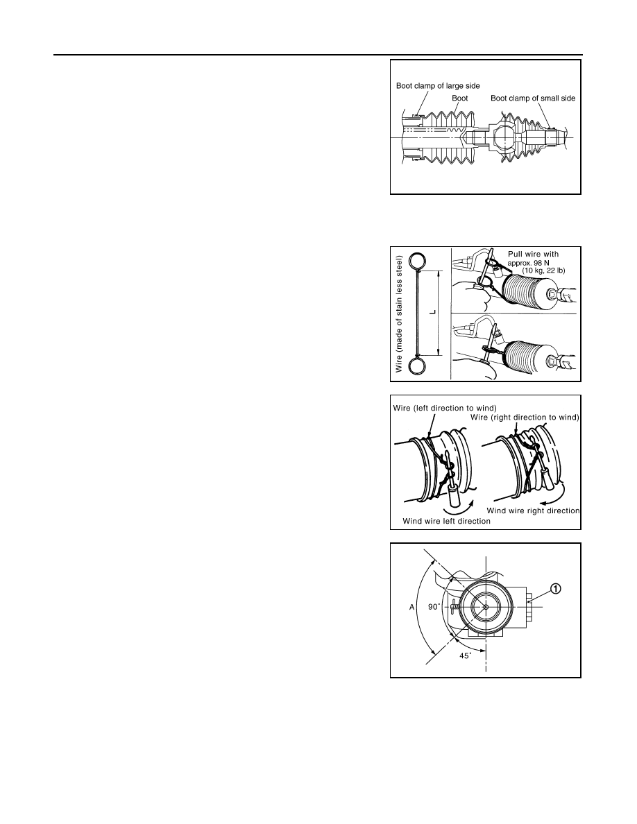
15. Install large end of boot to gear housing assembly.

16. Install small end of boot to inner socket boot mounting groove.
17. Install boot clamp to boot small end.

18. Install boot clamp to the large side of boot with the following procedure.

CAUTION:

Never reuse boot clamp.

a.

Tighten large side of boot with boot clamp (stainless wire).

b.

Wrap clamp around boot groove for two turns. Insert a flat-
bladed screwdriver in loops on both ends of wire. Twist 4 to 4.5
turns while pulling them with force of approximately 98 N (10 kg,
22 lb).

c.

Twist boot clamp as shown. Pay attention to relationship
between winding and twisting directions.

d.

Twisted area (A) of clamp is in the opposite side of adjusting
screw (1) as shown in the figure (to prevent contact with other
parts).

SGIA1325E

Wire length (L)

: 370 mm (14.57 in)

SGIA0163E

SGIA0164E

JSGIA0324ZZ

Revision: 2013 February

2012 MURANO

STEERING GEAR AND LINKAGE

ST-95

< REMOVAL AND INSTALLATION >

[WITHOUT HEATED STEERING WHEEL]

C

D

E

F

H

I

J

K

L

M

A

B

ST

N

O

P

e.

Bent cut end of the wire toward rack axial as shown in the figure
after twisting the wire 4 to 4.5 turns so that cut end does not con-
tact with boot.

19. Install cylinder tubes to gear housing assembly.

20. Install low pressure piping.

21. Adjust inner socket to standard length (L), and then tighten lock

nut (1) to the specified torque. Check length again after tighten-
ing lock nut.

CAUTION:

Adjust toe-in after this procedure. The length achieved after
toe-in adjustment is not necessary the above value.

Inspection

INFOID:0000000007540197

INSPECTION AFTER DISASSEMBLY

Boot

Check boot for cracks, and replace it if a malfunction is detected.

Rack Assembly

Check rack for damage or wear, and replace it if a malfunction is detected.

Gear-Sub Assembly

• Check gear-sub assembly for damage or wear, and replace it if a malfunction is detected.
• Rotate gear-sub assembly and check for torque variation or rattle, and replace it if a malfunction is detected.

Gear Housing Assembly

Check gear housing assembly for damage and scratches (inner wall). Replace if there are.

Outer Socket and Inner Socket

Check the following items and replace the component if it does not meet the standard.

BALL JOINT SWINGING TORQUE

Hook a spring balance at the point shown in the figure and pull the
spring balance. Make sure that the spring balance reads the speci-
fied value when ball stud and inner socket start to move. Replace
outer socket and inner socket if they are outside the standard.

A

: Gear housing RHD side

B

: Gear housing LHD side

JSGIA0325ZZ

Standard

Inner socket length (L)

: Refer to 

ST-106, "Inner 

Socket Length"

.

JPGIA0187ZZ

Standard

(Measuring point of outer socket: Stud cotter pin 
mounting hole)

Outer socket

: Refer to 

ST-106, "Socket 

Swing Force and Rotating 
Torque"

.

SGIA0896E

Revision: 2013 February

2012 MURANO

ST-96

< REMOVAL AND INSTALLATION >

[WITHOUT HEATED STEERING WHEEL]

STEERING GEAR AND LINKAGE

BALL JOINT ROTATING TORQUE

Make sure that the reading is within the following specified range
using preload gauge (A) [SST: ST3127S000 (J-25765-A)]. Replace
outer socket if the reading is outside the specified value.

BALL JOINT AXIAL END PLAY

Apply an axial load of 490 N (50 kg, 110 lb) to ball stud. Using a dial
gauge, measure amount of stud movement, and then make sure that
the value is within the following specified range. Replace outer
socket (1) and inner socket (2) if the measured value is outside the
standard.

INSPECTION AFTER INSTALLATION

• Check if steering wheel turns smoothly when it is turned several times fully to the end of the left and right.
• Check the steering wheel play, neutral position steering wheel, steering wheel turning force, and front wheel

turning angle. Refer to 

ST-77, "Inspection"

.

• Check the fluid level, fluid leakage, and air bleeding hydraulic system. Refer to 

ST-75, "Inspection"

.

Standard 

(Measuring point of inner socket: “*” mark shown in 
the figure)

Inner socket

: Refer to 

ST-106, "Socket 

Swing Force and Rotating 
Torque"

.

Standard

Rotating torque

: Refer to 

ST-106, "Socket 

Swing Force and Rotating 
Torque"

.

SGIA1382E

Standard

Outer socket

: Refer to 

ST-106, "Socket Axial 

End Play"

.

Inner socket

Refer to 

ST-106, "Socket Axial 

End Play"

.

JSGIA0109ZZ

Revision: 2013 February

2012 MURANO

POWER STEERING OIL PUMP

ST-97

< REMOVAL AND INSTALLATION >

[WITHOUT HEATED STEERING WHEEL]

C

D

E

F

H

I

J

K

L

M

A

B

ST

N

O

P

POWER STEERING OIL PUMP

Exploded View

INFOID:0000000007540198

REMOVAL

DISASSEMBLY

1.

Power steering oil pump

: Vehicle front

Refer to 

GI-4, "Components"

 for symbols in the figure.

JSGIA0326GB

1.

Pulley

2.

Oil seal

3.

Front bracket

4.

Suction pipe

5.

O-ring 

6.

Body assembly 

7.

Flow control valve spring

8.

Flow control valve 

9.

Flow control valve sub assembly

JSGIA0327GB

Revision: 2013 February

2012 MURANO

ST-98

< REMOVAL AND INSTALLATION >

[WITHOUT HEATED STEERING WHEEL]

POWER STEERING OIL PUMP

Removal and Installation

INFOID:0000000007540199

REMOVAL

1.

Drain power steering fluid from reservoir tank.

2.

Remove front road wheel and tires.

3.

Remove splash guard. Refer to 

EXT-23, "FENDER PROTECTOR : Exploded View"

.

4.

Loosen drive belt. Refer to 

EM-17, "Removal and Installation"

.

5.

Remove drive belt from oil pump pulley.

6.

Remove copper washers and eye bolt (drain fluid from their pipings).

7.

Remove suction hose (drain fluid from their pipings).

8.

Remove oil pump mounting bolts, and then remove oil pump.

CAUTION:

Never damage drive shaft boot.

INSTALLATION

Note the following, and install in the reverse order of removal.
• When installing suction hoses (1), refer to the figure.

CAUTION:

• Never apply fluid to the hose (1) and tube (2).
• Insert hose securely until it contacts spool (A) of tube.
• Leave clearance (L) when installing clamp (3).

• When installing eye bolt (1) and copper washers (2) to oil pump

(3), refer to the figure.

CAUTION:

• Never reuse copper washer.
• Apply power steering fluid to around copper washer, then

install eye bolt.

• Install eye bolt with eye joint (assembled to high pressure

hose) (B) protrusion (A) facing with pump side cutout, and
then tighten it to the specified torque after tightening by
hand. Refer to 

ST-103, "Exploded View"

.

• Securely insert harness connector to pressure sensor.

• Adjust belt tension. Refer to 

EM-17, "Tension Adjustment"

.

• Check fluid level, fluid leakage and air bleeding hydraulic system after the installation. Refer to 

ST-75,

"Inspection"

.

Disassembly and Assembly

INFOID:0000000007540200

DISASSEMBLY

1.

Remove rear bracket.

10. O-ring

11.

O-ring

12. Front side plate

13. Vane

14. Rotor

15. Cam ring 

16. Dowel pin

17. Rear side plate

18. O-ring

19. Teflon ring

20. Rear cover

21. Rear bracket

A.

Oil seal lip

: Apply power steering fluid.

: Apply multi-purpose grease.

Refer to 

GI-4, "Components"

 for symbols not described on the above.

Standard

L

: 3 – 8 mm (0.12 – 0.31 in)

JSGIA0118ZZ

SGIA1379E

Revision: 2013 February

2012 MURANO

POWER STEERING OIL PUMP

ST-99

< REMOVAL AND INSTALLATION >

[WITHOUT HEATED STEERING WHEEL]

C

D

E

F

H

I

J

K

L

M

A

B

ST

N

O

P

2.

Remove rear cover mounting bolts, and then remove rear cover from body assembly.

CAUTION:

• Fix oil pump with a vise if necessary.
• Use copper plates when fixing with a vise.

3.

Remove O-ring from body assembly.

4.

Remove rear side plate from cartridge, and then remove Teflon ring and O-ring from rear side plate.

5.

Remove rotor snap ring (1) using a snap ring pliers, and remove
cam ring, rotor and vane from body assembly.

CAUTION:

When removing the snap ring, never damage the pulley
shaft.

6.

Remove front side plate.

7.

Remove cartridge, flow control valve (1), flow control valve
spring (2) and flow control valve sub assembly (3) from body
assembly (4).

CAUTION:

Never drop and damage flow control valve and flow control
valve sub assembly when removing.

8.

Remove oil seal from body assembly.

9.

Remove mounting bolt of suction pipe, and then remove suction
pipe from body assembly.

10. Remove pulley from body assembly.
11. Remove front bracket from body assembly.

12. Remove oil seal from body assembly using a flat-bladed screw-

driver.

CAUTION:

Never damage the body assembly.

ASSEMBLY

1.

Apply recommended grease to oil seal lips (1). Apply recom-
mended fluid to around oil seal. Install oil seal to body assembly
using a drift (commercial service tool).

CAUTION:

• Never reuse the oil seal.
• Fix oil pump with a vise if necessary.
• Use copper plates when fixing with a vise.

2.

Install front bracket to body assembly.

3.

Install pulley to body assembly.

4.

If dowel pin has been removed, insert it into body assembly by
hand. If it cannot be inserted by hand, lightly tap with a hammer.

JSGIA0328ZZ

JSGIA0329ZZ

JSGIA0331ZZ

JSGIA0330ZZ

Revision: 2013 February

2012 MURANO

ST-100

< REMOVAL AND INSTALLATION >

[WITHOUT HEATED STEERING WHEEL]

POWER STEERING OIL PUMP

5.

Install flow control valve (1), flow control valve spring (2) and
flow control valve sub assembly (3) as shown in the figure to
body assembly (4).

6.

Install front side plate (3) with dowel pin (2) on flow control valve
A (1) side as shown in the figure aligning with front side plate
cutout (A) to body assembly (4).

7.

Install cam ring as shown in the figure.

8.

Install rotor so that mark faces body assembly, and then install it
to pulley shaft.

9.

Install vane to rotor so that arc of vane faces cam ring side.

10. Install rotor snap ring to slit of pulley shaft using a hammer and a

drift (commercial service tool).

CAUTION:

• Never damage rotor and pulley shaft.
• Oil pump assembly must be replaced if rotor is damaged.

JSGIA0329ZZ

SGIA1189E

SGIA0612E

SGIA0989E

SGIA0613E

Revision: 2013 February

2012 MURANO

POWER STEERING OIL PUMP

ST-101

< REMOVAL AND INSTALLATION >

[WITHOUT HEATED STEERING WHEEL]

C

D

E

F

H

I

J

K

L

M

A

B

ST

N

O

P

11. Install rear side plate with dowel pin A on flow control valve A

side as shown in the figure aligning with rear side plate cutout B
to cartridge.

12. Apply recommended fluid to O-ring, and then install O-ring to

body assembly.

13. Apply recommended fluid to O-ring, and then install O-ring to

rear side plate.

14. Apply recommended fluid to Teflon ring, and then install Teflon

ring to rear side plate.

15. Install rear cover to body assembly.

16. Apply recommended fluid to O-ring, and then install O-ring to

body assembly.

17. Install suction pipe to body assembly.

18. Install rear bracket.

Inspection

INFOID:0000000007540201

RELIEF OIL PRESSURE

CAUTION:

Make sure that belt tension is normal before starting the following procedure.
1.

Connect the oil pressure gauge [SST: KV48103500 (J-26357)]
and the oil pressure gauge adapter [SST: KV48102500 (J-
33914)] between oil pump discharge connector and high-pres-
sure hose. Bleed air from the hydraulic circuit while opening
valve fully. Refer to 

ST-75, "Inspection"

.

2.

Start the engine. Run the engine until oil temperature reaches
50 to 80

°

C (122 to 176

°

F).

CAUTION:

• Leave the valve of the oil pressure gauge fully open while

starting and running the engine. If engine is started with
the valve closed, the hydraulic pressure in oil pump goes
up to the relief pressure along with unusual increase of oil
temperature.

• Be sure to keep hose clear of belts and other parts when

engine is started.

3.

Fully close the oil pressure gauge valve with engine at idle and
measure the relief oil pressure.

CAUTION:

Never keep valve closed for 10 seconds or longer.

4.

Open the valve slowly after measuring. Repair oil pump if the relief oil pressure is outside the standard.
Refer to 

ST-98, "Disassembly and Assembly"

.

5.

Disconnect the oil pressure gauge from hydraulic circuit.

PGIA0035E

Standard

Relief oil pressure

: Refer to 

ST-106, "Relief 

Oil Pressure"

.

SGIA0915E

Revision: 2013 February

2012 MURANO

ST-102

< REMOVAL AND INSTALLATION >

[WITHOUT HEATED STEERING WHEEL]

POWER STEERING OIL PUMP

6.

When installing eye bolt (1) and copper washers (2) to oil pump
(3), refer to the figure.

CAUTION:

• Never reuse copper washer.
• Apply power steering fluid or equivalent to around copper

washer, then install eye bolt.

• Install eye bolt with eye joint (assembled to high pressure

hose) (B) protrusion (A) facing with pump side cutout, and
then tighten it to the specified torque after tightening by
hand. Refer to 

ST-103, "Exploded View"

.

• Securely insert harness connector to pressure sensor.

7.

Check fluid level, fluid leakage and air bleeding hydraulic sys-
tem after the installation. Refer to 

ST-75, "Inspection"

.

BEFORE DISASSEMBLY

Disassemble oil pump only when the following malfunctions occur.
• If oil leakage is found on oil pump.
• Oil pump pulley is damaged or deformed.
• Performance of oil pump is low. 

AFTER DISASSEMBLY

Body Assembly and Rear Cover Inspection

• Check body assembly and rear cover for internal damage. Replace rear cover if it is damaged. Replace oil

pump assembly if body assembly is damaged.

Cartridge Assembly Inspection

• Check cam ring, rotor and vane for damage. Replace cartridge assembly if necessary.

Side Plate Inspection

• Check side plate for damage. Replace side plate if necessary.

Flow Control Valve Inspection

• Check flow control valve and spring for damage. Replace if necessary.

SGIA1379E

Revision: 2013 February

2012 MURANO

HYDRAULIC LINE

ST-103

< REMOVAL AND INSTALLATION >

[WITHOUT HEATED STEERING WHEEL]

C

D

E

F

H

I

J

K

L

M

A

B

ST

N

O

P

HYDRAULIC LINE

Exploded View

INFOID:0000000007540202

Removal and Installation

INFOID:0000000007540203

CAUTION:

1.

Reservoir tank bracket

2.

Bushing

3.

Reservoir tank

4.

Suction hose

5.

Clamp

6.

Copper washer

7.

High pressure piping

8.

Steering gear assembly

9.

Low pressure hose

10. Eye bolt

A.

To power steering oil pump suction 
hose.

B.

To power steering oil pump.

: Vehicle front

: Apply power steering fluid.

Refer to 

GI-4, "Components"

 for symbols not described on the above.

JSGIA0608GB

Revision: 2013 February

2012 MURANO

ST-104

< REMOVAL AND INSTALLATION >

[WITHOUT HEATED STEERING WHEEL]

HYDRAULIC LINE

• Never apply fluid to the hose (1) and tube (2).
• Insert hose securely until it contacts spool (A) of tube.
• Leave clearance (L) when installing clamp (3).

• Install eye bolt with eye joint (assembled to high pressure

hose) (B) protrusion (A) facing with pump side cutout, and
then tighten it to the specified torque after tightening by hand.
Refer to 

ST-103, "Exploded View"

.

• Securely insert harness connector to pressure sensor.
• Apply power steering fluid to around copper washer, then

install eye bolt.

• Never reuse copper washer.

Standard

L

: 3 – 8 mm (0.12 – 0.31 in)

JSGIA0118ZZ

SGIA1379E

Revision: 2013 February

2012 MURANO

SERVICE DATA AND SPECIFICATIONS (SDS)

ST-105

< SERVICE DATA AND SPECIFICATIONS (SDS) 

[WITHOUT HEATED STEERING WHEEL]

C

D

E

F

H

I

J

K

L

M

A

B

ST

N

O

P

SERVICE DATA AND SPECIFICATIONS (SDS)

SERVICE DATA AND SPECIFICATIONS (SDS)

General Specifications

INFOID:0000000007540204

Steering Wheel Axial End Play and Play

INFOID:0000000007540205

Unit: mm (in)

Steering Wheel Turning Force

INFOID:0000000007540206

Unit: N·m (kg-m, in-lb)

Steering Angle

INFOID:0000000007540207

Unit: Degree minute (Decimal degree)

Steering Column Length

INFOID:0000000007540208

Unit: mm (in)

Steering Column Mounting Dimensions

INFOID:0000000007540209

Unit: mm (in)

Steering Column Operating Range

INFOID:0000000007540210

Steering gear model

PR26AF

Fluid capacity (Approx.)

 (US qt, lmp qt)

1.0 (1-1/8, 7/8)

Item

Standard

Steering wheel axial end play

0 (0)

Steering wheel play on the outer circumference

0 – 35 (0 – 1.38)

Item

Standard

Steering wheel turning force

7.45 (0.76, 66)

Item

Standard

Wheel size: 18 inch

Wheel size: 20 inch

Inner wheel

Minimum

33

°

30

 (33.5

°

)

32

°

00

 (32.0

°

)

Nominal

36

°

30

 (36.5

°

)

35

°

00

 (35.0

°

)

Maximum

37

°

30

 (37.5

°

)

36

°′

 (36.0

°

)

Outer wheel

Nominal

31

°

30

 (31.5

°

)

30

°

30

 (30.5

°

)

Item

Standard

Steering column length

463 (18.23)

Item

Standard

Mounting dimension

30 (1.18) or less

Item

Standard

Tilt operating range 

15

°

Telescopic operating range 

40 mm (1.57 in)

Rotating torque

0.49 N·m (0.05 kg-m, 4 in-lb)

Revision: 2013 February

2012 MURANO

ST-106

< SERVICE DATA AND SPECIFICATIONS (SDS) 

[WITHOUT HEATED STEERING WHEEL]

SERVICE DATA AND SPECIFICATIONS (SDS)

Lower Shaft Length

INFOID:0000000007540211

Unit: mm (in)

Rack Sliding Force

INFOID:0000000007540212

Unit: N (kg, lb)

Rack Stroke

INFOID:0000000007540213

Unit: mm (in)

Socket Swing Force and Rotating Torque

INFOID:0000000007540214

SWING FORCE

Unit: N (kg, lb)

ROTATING TORQUE

Unit: N·m (kg-m, in-lb)

Socket Axial End Play

INFOID:0000000007540215

Unit: mm (in)

Inner Socket Length

INFOID:0000000007540216

Unit: mm (in)

Relief Oil Pressure

INFOID:0000000007540217

Unit: kPa (kg/cm

2

, psi)

Item

Standard

Lower shaft length (extended position)

524.6 – 525.6 (20.65 – 20.69)

Item

Standard

2WD

AWD

Rack sliding force

195 – 258 (19.9 – 26.3, 43.8 – 

57.9)

227 – 305 (23.2 – 31.1, 51.1 – 

68.5)

Item

Standard

Wheel size: 18 inch

Wheel size: 20 inch

Rack stroke neutral position

70.5 (2.776)

68.0 (2.677)

Item

Standard

Outer socket

4.81 – 45.7 (0.5 – 4.6, 1.1 – 10.2)

Inner socket

8.9 – 64 (0.91 – 6.5, 2.01 – 14.3)

Item

Standard

Outer socket 

0.3 – 2.9 (0.03 – 0.29, 3 – 25)

Item

Standard

Outer socket

0.5 (0.02) or less

Inner socket

0.2 (0.008) or less

Item

Standard

Inner socket length

120.3 (4.74)

Item

Standard

Relief oil pressure

9,500 – 10,300 (96.9 – 105.1, 1,378 – 1,494)

Revision: 2013 February

2012 MURANO

STC-1

STEERING

C

D

E

F

H

I

J

K

L

M

SECTION 

STC

A

B

STC

N

O

P

CONTENTS

STEERING CONTROL SYSTEM

BASIC INSPECTION  ....................................

2

DIAGNOSIS AND REPAIR WORK FLOW  .........

2

Work Flow  .................................................................

2

SYSTEM DESCRIPTION  ..............................

3

EPS SYSTEM  ......................................................

3

System Diagram ........................................................

3

System Description  ...................................................

3

Component Parts Location ........................................

5

Component Description .............................................

5

DTC/CIRCUIT DIAGNOSIS  ..........................

6

POWER SUPPLY AND GROUND CIRCUIT .......

6

Description ................................................................

6

Diagnosis Procedure .................................................

6

POWER STEERING SOLENOID VALVE  ...........

7

Description ................................................................

7

Diagnosis Procedure .................................................

7

Component Inspection  ..............................................

8

ENGINE SPEED SIGNAL CIRCUIT  ....................

9

Description ................................................................

9

Diagnosis Procedure .................................................

9

VEHICLE SPEED SIGNAL CIRCUIT  .................

11

Description ..............................................................

11

Diagnosis Procedure ...............................................

11

ECU DIAGNOSIS INFORMATION ..............

13

POWER STEERING CONTROL UNIT ..............

13

Reference Value ......................................................

13

Wiring Diagram - ELECTRONICALLY CON-
TROLLED POWER STEERING SYSTEM -  ............

15

Fail-Safe ..................................................................

15

SYMPTOM DIAGNOSIS  ..............................

17

UNBALANCE STEERING WHEEL TURNING 
FORCE (TORQUE VARIATION) .......................

17

Description ...............................................................

17

Diagnosis Procedure  ...............................................

17

PRECAUTION ..............................................

18

PRECAUTIONS .................................................

18

FOR USA AND CANADA  ..........................................

18

FOR USA AND CANADA : Precaution for Supple-
mental Restraint System (SRS) "AIR BAG" and 
"SEAT BELT PRE-TENSIONER" ............................

18

FOR MEXICO .............................................................

18

FOR MEXICO : Precaution for Supplemental Re-
straint System (SRS) "AIR BAG" and "SEAT BELT 
PRE-TENSIONER" ..................................................

18

REMOVAL AND INSTALLATION  ...............

20

POWER STEERING CONTROL UNIT ..............

20

Removal and Installation  .........................................

20

Revision: 2013 February

2012 MURANO

STC-2

< BASIC INSPECTION >

DIAGNOSIS AND REPAIR WORK FLOW

BASIC INSPECTION

DIAGNOSIS AND REPAIR WORK FLOW

Work Flow

INFOID:0000000007540088

DETAILED FLOW

1.

COLLECT THE INFORMATION FROM THE CUSTOMER

It is also important to clarify customer complaints before inspection. First of all, reproduce symptoms and
understand them fully. Ask customer about his/her complaints carefully. In some cases, it is necessary to
check symptoms by driving vehicle with customer.

CAUTION:

Customers are not professional. It is dangerous to make an easy guess like “maybe the customer
means that...,” or “maybe the customer mentions this symptom”.

>> GO TO 2.

2.

CHECK THE STATUS

1.

Power steering fluid leakage and check the power steering fluid level. Refer to 

ST-31, "Inspection"

.

2.

Check the drive belt tension. Refer to 

EM-17, "Checking"

.

3.

Check the power steering gear for damages, cracks and fluid leakage. Refer to 

ST-54, "Inspection"

.

4.

Check the relief oil pressure. Refer to 

ST-60, "Inspection"

 (With heated steering wheel), 

ST-101, "Inspec-

tion"

 (Without heated steering wheel).

>> GO TO 3.

3.

DIAGNOSIS CHART BY SYMPTOM

Perform the diagnosis by symptom. Refer to 

STC-17, "Diagnosis Procedure"

.

>> GO TO 4.

4.

FINAL CHECK

Check the input/output standard values for the power steering control unit.

Are the power steering control unit input/output values within standard ranges respectively?

YES

>> INSPECTION END

NO

>> GO TO 2.

Revision: 2013 February

2012 MURANO

EPS SYSTEM

STC-3

< SYSTEM DESCRIPTION >

C

D

E

F

H

I

J

K

L

M

A

B

STC

N

O

P

SYSTEM DESCRIPTION

EPS SYSTEM

System Diagram

INFOID:0000000007540089

CONTROL DIAGRAM

CROSS-SECTIONAL VIEW

System Description

INFOID:0000000007540090

• The EPS system controls the power steering solenoid valve through the power steering control unit.

JSGIA0119GB

1.

Combination meter

2.

Power steering control unit

3.

Power steering solenoid valve

4.

Steering gear assembly

5.

Gear housing assembly

6.

Gear sub-assembly

7.

Pinion

8.

Power steering oil pump

9.

Reservoir tank

JSGIA0376ZZ

Revision: 2013 February

2012 MURANO


Content      ..     86      87      88      89     ..