Nissan Murano Z51 (2012 year). Manual - part 59


  Index      Manuals     Nissan Murano Z51 (2012 year) - Service and Repair Manual


Search            copyright infringement  


Content      ..     57      58      59      60     ..


Nissan Murano Z51 (2012 year). Manual - part 59


MWI-56

< DTC/CIRCUIT DIAGNOSIS >

A/C AUTO AMP. CONNECTION RECOGNITION SIGNAL CIRCUIT

A/C AUTO AMP. CONNECTION RECOGNITION SIGNAL CIRCUIT

Description

INFOID:0000000007543136

A/C auto amp. transmit the A/C auto amp. connection recognition signal to the combination meter.

Diagnosis Procedure

INFOID:0000000007543137

1.

CHECK A/C AUTO AMP. CONNECTION RECOGNITION SIGNAL

1.

Turn ignition switch ON.

2.

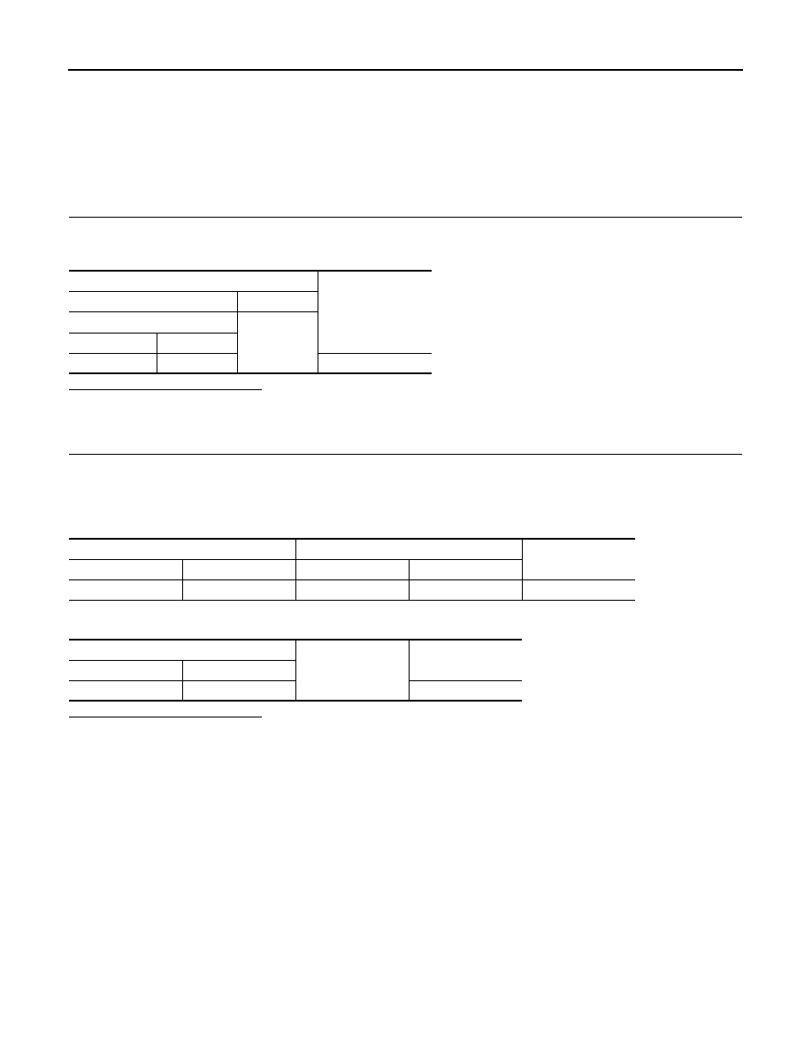
Check voltage between combination meter harness connector terminal and ground.

Is the inspection result normal?

YES

>> INSPECTION END

NO

>> GO TO 2.

2.

CHECK A/C AUTO AMP. CONNECTION RECOGNITION SIGNAL CIRCUIT

1.

Turn ignition switch OFF.

2.

Disconnect combination meter connector and A/C auto amp. connector.

3.

Check continuity between combination meter harness connector terminal and A/C auto amp. harness
connector terminal.

4.

Check continuity between combination meter harness connector and ground.

Is the inspection result normal?

YES

>> INSPECTION END

NO

>> Repair harness or connector.

Terminals

Voltage

(Approx.)

(+)

(-)

Combination meter

Ground

Connector

Terminal

M34

19

5 V

Combination meter

A/C auto amp.

Continuity

Connector

Terminal

Connector

terminal

M34

19

M50

34

Existed

Combination meter

Ground

Continuity

Connector

Terminal

M34

19

Not existed

Revision: 2013 February

2012 MURANO

MWI

COMPASS

MWI-57

< DTC/CIRCUIT DIAGNOSIS >

C

D

E

F

G

H

I

J

K

L

M

B

A

O

P

COMPASS

Wiring Diagram - COMPASS -

INFOID:0000000007543138

For connector terminal arrangements, harness layouts, and alphabets in a 

(option abbreviation; if not

described in wiring diagram), refer to 

GI-12, "Connector Information"

.

JCNWM5352GB

Revision: 2013 February

2012 MURANO

MWI-58

< ECU DIAGNOSIS INFORMATION >

COMBINATION METER

ECU DIAGNOSIS INFORMATION

COMBINATION METER

Reference Value

INFOID:0000000007543139

VALUES ON THE DIAGNOSIS TOOL

Monitor Item

Condition

Value/Status

SPEED METER
[km/h]

Ignition switch 
ON

While driving

Equivalent to speedometer reading
NOTE:
655.35 is displayed when the malfunc-
tion signal is received

SPEED OUTPUT
[km/h]

Ignition switch 
ON

While driving

Equivalent to speedometer reading
NOTE:
655.35 is displayed when the malfunc-
tion signal is received

ODO OUTPUT
[km/h or mph]

Ignition switch 
ON

Equivalent to odometer reading in 
combination meter

TACHO METER
[rpm]

Ignition switch 
ON

While driving

Equivalent to tachometer reading
NOTE:
8191.875 is displayed when the mal-
function signal is received

FUEL METER
[L]

Ignition switch 
ON

Values according to fuel level

W TEMP METER
[

°

C]

Ignition switch 
ON

Values according to engine coolant 
temperature
NOTE:
215 is displayed when the malfunction 
signal is input

FUEL CAP W/L

Ignition switch 
ON

Fuel filler cap warning display ON

On

Fuel filler cap warning display OFF

Off

ABS W/L

Ignition switch 
ON

ABS warning lamp ON

On

ABS warning lamp OFF

Off

VDC/TCS IND

Ignition switch 
ON

VDC OFF indicator lamp ON

On

VDC OFF indicator lamp OFF

Off

SLIP IND

Ignition switch 
ON

VDC warning lamp ON

On

VDC waning lamp OFF

Off

BRAKE W/L

Ignition switch 
ON

Brake warning lamp ON

On

Brake warning lamp OFF

Off

DOOR W/L

Ignition switch 
ON

Door warning lamp ON

On

Door warning lamp OFF

Off

HI-BEAM IND

Ignition switch 
ON

High-beam indicator lamp ON

On

High-beam indicator lamp OFF

Off

TURN IND

Ignition switch 
ON

Turn signal indicator lamp ON

On

Turn signal indicator lamp OFF

Off

LIGHT IND

Ignition switch 
ON

Light indicator lamp ON

On

Light indicator lamp OFF

Off

OIL W/L 

Ignition switch 
ON

Oil pressure warning lamp ON

On

Oil pressure warning lamp OFF

Off

MIL

Ignition switch 
ON

Malfunction indicator lamp ON

On

Malfunction indicator lamp OFF

Off

Revision: 2013 February

2012 MURANO

MWI

COMBINATION METER

MWI-59

< ECU DIAGNOSIS INFORMATION >

C

D

E

F

G

H

I

J

K

L

M

B

A

O

P

CRUISE IND

Ignition switch 
ON

CRUISE indicator lamp ON

On

CRUISE indicator lamp OFF

Off

O/D OFF IND

Ignition switch 
ON

O/D OFF indicator lamp ON

On

O/D OFF indicator lamp OFF

Off

4WD W/L

Ignition switch 
ON

AWD warning lamp ON

On

AWD warning lamp OFF

Off

4WD LOCK IND

Ignition switch 
ON

AWD LOCK indicator lamp ON

On

AWD LOCK indicator lamp OFF

Off

FUEL W/L

Ignition switch 
ON

Low-fuel warning lamp ON

On

Low-fuel warning lamp OFF

Off

WASHER W/L

Ignition switch 
ON

Washer warning displayed

On

Washer warning not displayed

Off

AIR PRES W/L

Ignition switch 
ON

Low tire pressure lamp ON

On

Low tire pressure lamp OFF

Off

KEY G/Y W/L 

Ignition switch 
ON

Key warning lamp (green/yellow) ON

On

Key warning lamp (green/yellow) OFF

Off

LCD

Ignition switch 
ON

Engine start information display

B&P I

Ignition switch 
ACC

Engine start information display

B&P N

Ignition switch 
LOCK

Key ID warning display

ID NG

Ignition switch 
LOCK

Steering lock information display

ROTAT

Ignition switch 
LOCK

P position warning display

SFT P

Ignition switch 
LOCK

Intelligent Key insert information display

INSRT

Ignition switch 
LOCK

Intelligent Key low battery warning display

BATT

Ignition switch 
ON

Take away warning display

NO KY

Ignition switch 
LOCK

Key warning display

OUTKY

Ignition switch 
ON

ACC warning display

LK WN

SHIFT IND

Ignition switch 
ON

Shift position indicator P display

P

Shift position indicator R display

R

Shift position indicator N display

N

Shift position indicator D display

D

Shift position indicator L display

L

O/D OFF SW

Ignition switch 
ON

Overdrive control switch ON

On

Overdrive control switch OFF

Off

M RANGE SW

Ignition switch 
ON

NOTE:
This item is displayed, but cannot be moni-
tored.

Off

NM RANGE SW

Ignition switch 
ON

NOTE:
This item is displayed, but cannot be moni-
tored.

Off

Monitor Item

Condition

Value/Status

Revision: 2013 February

2012 MURANO

MWI-60

< ECU DIAGNOSIS INFORMATION >

COMBINATION METER

NOTE:

Some items are not available according to vehicle specification.

TERMINAL LAYOUT

PHYSICAL VALUES

AT SFT UP SW

Ignition switch 
ON

NOTE:
This item is displayed, but cannot be moni-
tored.

Off

AT SFT DWN SW

Ignition switch 
ON

NOTE:
This item is displayed, but cannot be moni-
tored.

Off

ST SFT UP SW

Ignition switch 
ON

NOTE:
This item is displayed, but cannot be moni-
tored.

Off

ST SFT DWN SW

Ignition switch 
ON

NOTE:
This item is displayed, but cannot be moni-
tored.

Off

PKB SW

Ignition switch 
ON

Parking brake switch ON

On

Parking brake switch OFF

Off

BUCKLE SW

Ignition switch 
ON

Seat belt (driver side) not fastened

On

Seat belt (driver side) fastened

Off

BRAKE OIL SW

Ignition switch 
ON

Brake fluid level switch ON

On

Brake fluid level switch OFF

Off

DISTANCE
[km]

Ignition switch 
ON

Possible driving distance calculated by 
combination meter

A/C AMP CONN

Ignition switch 
ON

Other than the following

On

Receives ambient sensor power signal

Off

ENTER SW

Ignition switch 
ON

When 

 is pressed

On

Other than the above

Off

SELECT SW

Ignition switch 
ON

When 

 is pressed

On

Other than the above

Off

OUTSIDE TEMP
[

°

C] or [

°

F]

Ignition switch 
ON

Equivalent to ambient temperature
NOTE:
This may not match the indicated value 
on the information display.

FUEL LOW SIG

Ignition switch 
ON

Low fuel warning displayed

On

Low fuel warning not displayed

Off

BUZZER

Ignition switch 
ON

Buzzer ON

On

Buzzer OFF

Off

Monitor Item

Condition

Value/Status

JPNIA0968GB

Revision: 2013 February

2012 MURANO

MWI

COMBINATION METER

MWI-61

< ECU DIAGNOSIS INFORMATION >

C

D

E

F

G

H

I

J

K

L

M

B

A

O

P

Terminal No.

(Wire color)

Description

Condition

Value

(Approx.)

+

Signal name

Input/

Output

1

(Y)

Ground

Battery power supply

Input

Ignition 
switch 
OFF

Battery voltage

2

(LG)

Ground

IGN signal

Input

Ignition 
switch 
ON

Battery voltage

3

(B)

Ground

Ground

Ignition 
switch 
ON

0  V

5

(SB)

Ground

Illumination control signal

Output

Ignition 
switch 
ON

• Lighting switch 1ST
• When meter illumination 

is maximum

• Lighting switch 1ST
• When meter illumination 

is minimum

8

(SB)

10

(LG)

Trip reset signal

Input

Ignition 
switch 
ON

When trip reset switch is 
pressed.

0 V

Other than the above

5 V

10

(LG)

Ground

Meter control switch ground

Ignition 
switch 
ON

0  V

11

(L)

10

(LG)

Enter switch signal

Input

Ignition 
switch 
ON

When 

 is pressed.

0 V

Other than the above

5 V

12

(R)

10

(LG)

Select switch signal

Input

Ignition 
switch 
ON

When  

is 

pressed.

0 V

Other than the above

5 V

13

(Y

*1

 or 

V

*2

)

10

(LG)

Illumination control switch 
signal (+)

Input

Ignition 
switch 
ON

When 

 is pressed.

0 V

Other than the above

5 V

14

(GR)

10

(LG)

Illumination control switch 
signal (-)

Input

Ignition 
switch 
ON

When 

 is pressed.

0 V

Other than the above

5 V

15

(BR)

Ground

Air bag signal

Input

Ignition 
switch 
ON

Air bag warning lamp
ON

4 V

Air bag warning lamp
OFF

0 V

JPNIA0828GB

JPNIA0827GB

Revision: 2013 February

2012 MURANO

MWI-62

< ECU DIAGNOSIS INFORMATION >

COMBINATION METER

18

(L)

Ground

Ambient sensor signal

Input

Ignition 
switch 
ON

Changes depending to am-
bient temperature.

19

(P)

Ground

Ambient sensor power

Input

Ignition 
switch 
ON

5  V

20

(Y)

Ground

Ambient sensor ground

Input

Ignition 
switch 
ON

0  V

21

(L)

CAN-H

22

(P)

CAN-L

23

(B)

Ground

Ground

Ignition 
switch 
ON

0  V

24

(W)

Ground

Fuel level sensor ground

Ignition 
switch 
ON

0  V

25

(BR)

Ground

Alternator signal

Input

Ignition 
switch 
ON

Charge warning lamp ON

2 V

Charge warning lamp OFF

12 V

26

(G)

Ground

Parking brake switch signal

Input

Ignition 
switch 
ON

Parking brake ON

0 V

Parking brake OFF

5 V

27

(V)

Ground

Brake fluid level switch sig-
nal

Input

Ignition 
switch 
ON

Brake fluid level is normal

12 V

Brake fluid level is less than 
LOW level

0 V

29

(R)

Ground

Washer level switch signal

Input

Ignition 
switch 
ON

Washer level switch ON

0 V

Washer level switch OFF

5 V

30

(P)

Ground

Vehicle speed signal
(2-pulse)

Output

Ignition 
switch 
ON

Speedometer operated 
[When vehicle speed is ap-
prox. 40 km/h (25 MPH)]

NOTE:
The maximum voltage varies de-
pending on the specification 
(destination unit).

Terminal No.

(Wire color)

Description

Condition

Value

(Approx.)

+

Signal name

Input/

Output

JSNIA0014GB

JSNIA0015GB

Revision: 2013 February

2012 MURANO

MWI

COMBINATION METER

MWI-63

< ECU DIAGNOSIS INFORMATION >

C

D

E

F

G

H

I

J

K

L

M

B

A

O

P

*1: Without automatic drive positioner

*2: With automatic drive positioner

31

(V)

Ground

Vehicle speed signal
(8-pulse)

Output

Ignition 
switch 
ON

Speedometer operated 
[When vehicle speed is ap-
prox. 40 km/h (25 MPH)]

NOTE:
The maximum voltage varies de-
pending on the specification 
(destination unit).

32

(LG)

Ground

Overdrive control switch 
signal

Input

Ignition 
switch 
ON

Overdrive control switch 
pressed.

0 V

Overdrive control switch 
not pressed.

12 V

34

(G)

Ground

Fuel level sensor signal

Input

Ignition 
switch 
ON

35

(SB)

Ground

Seat belt buckle switch sig-
nal (driver side)

Input

Ignition 
switch 
ON

When driver seat belt is fas-
tened.

12 V

When driver seat belt is un-
fastened.

0 V

36

(R)

Ground

Seat belt buckle switch sig-
nal (passenger side)

Input

Ignition 
switch 
ON

• When getting in the pas-

senger seat.

• When passenger seat 

belt is fastened.

12 V

• When getting in the pas-

senger seat.

• When passenger seat 

belt is unfastened.

0 V

Terminal No.

(Wire color)

Description

Condition

Value

(Approx.)

+

Signal name

Input/

Output

JSNIA0012GB

JPNIA0740ZZ

Revision: 2013 February

2012 MURANO

MWI-64

< ECU DIAGNOSIS INFORMATION >

COMBINATION METER

Wiring Diagram - METER -

INFOID:0000000007543140

For connector terminal arrangements, harness layouts, and alphabets in a 

(option abbreviation; if not

described in wiring diagram), refer to 

GI-12, "Connector Information"

.

JCNWM5340GB

Revision: 2013 February

2012 MURANO

MWI

COMBINATION METER

MWI-65

< ECU DIAGNOSIS INFORMATION >

C

D

E

F

G

H

I

J

K

L

M

B

A

O

P

JCNWM5341GB

Revision: 2013 February

2012 MURANO

MWI-66

< ECU DIAGNOSIS INFORMATION >

COMBINATION METER

Fail-Safe

INFOID:0000000007543141

FAIL-SAFE

The combination meter activates the fail-safe control if CAN communication with each unit is malfunctioning.

JCNWM5342GB

Revision: 2013 February

2012 MURANO

MWI

COMBINATION METER

MWI-67

< ECU DIAGNOSIS INFORMATION >

C

D

E

F

G

H

I

J

K

L

M

B

A

O

P

DTC Index

INFOID:0000000007543142

Function

Specifications

Speedometer

Reset to zero by suspending communication.

Tachometer

Engine coolant temperature gauge

Illumination control

When suspending communication, changes to nighttime 
mode.

Information display

Door open warning

The display turns off by suspending communication.

Parking brake release warning

Low tire pressure warning

Fuel filler cap warning

Instantaneous fuel warning

• When reception time of an abnormal signal is 2 seconds or 

less, the last received datum is used for calculation to indi-
cate the result.

• When reception time of an abnormal signal is more than two 

seconds, the last result calculated during normal condition 
is indicated.

Average fuel consumption

Average vehicle speed

Travel distance

Buzzer

The buzzer turns off by suspending communication.

Warning lamp/indicator 
lamp

ABS warning lamp

The lamp turns on by suspending communication.

Brake warning lamp

AWD warning lamp

Malfunction indicator lamp

Low tire pressure warning lamp

The lamp turns ON after flashing for 1 minute.

High beam indicator lamp

The lamp turns off by suspending communication.

Turn signal indicator lamp

Light indicator lamp

Oil pressure warning lamp

CRUISE indicator lamp

O/D OFF indicator lamp

VDC warning lamp

VDC OFF indicator lamp

AWD LOCK indicator lamp

Key warning lamp

Display contents of CONSULT

Diagnostic item is detected when ...

Refer to

CAN COMM CIRCUIT
[U1000]

When combination meter is not transmitting or receiving CAN communication signal 
for 2 seconds or more.

MWI-39, 

"Diagnosis

Procedure"

CONTROL UNIT (CAN)
[U1010]

When detecting error during the initial diagnosis of the CAN controller of combina-
tion meter.

MWI-40, 

"Diagnosis 

Procedure"

VEHICLE SPEED
[B2205]

The abnormal vehicle speed signal is input from the ABS actuator and electric unit 
(control unit) for 2 seconds or more.

MWI-41, 

"Diagnosis

Procedure"

Revision: 2013 February

2012 MURANO

MWI-68

< ECU DIAGNOSIS INFORMATION >

COMBINATION METER

ENGINE SPEED
[B2267]

If ECM continuously transmits abnormal engine speed signals for 2 seconds or 
more.

MWI-42, 

"Diagnosis 

Procedure"

WATER TEMP
[B2268]

If ECM continuously transmits abnormal engine coolant temperature signals for 60 
seconds or more.

MWI-43, 

"Diagnosis 

Procedure"

Display contents of CONSULT

Diagnostic item is detected when ...

Refer to

Revision: 2013 February

2012 MURANO

MWI

IPDM E/R (INTELLIGENT POWER DISTRIBUTION MODULE ENGINE ROOM)

MWI-69

< ECU DIAGNOSIS INFORMATION >

C

D

E

F

G

H

I

J

K

L

M

B

A

O

P

IPDM E/R (INTELLIGENT POWER DISTRIBUTION MODULE ENGINE
ROOM)

Reference Value

INFOID:0000000007793821

VALUES ON THE DIAGNOSIS TOOL

Monitor Item

Condition

Value/Status

MOTOR FAN REQ

Engine idle speed

Changes depending on engine 
coolant temperature, air conditioner 
operation status, vehicle speed, 
etc.

1/2/3/4 

AC COMP REQ

Engine running

A/C switch OFF

Off

A/C switch ON
(Compressor is operating)

On

TAIL&CLR REQ

Lighting switch OFF

Off

Lighting switch 1ST, 2ND, HI or AUTO (Light is illuminated)

On

HL LO REQ

Lighting switch OFF

Off

Lighting switch 2ND HI or AUTO (Light is illuminated)

On

HL HI REQ

Lighting switch OFF

Off

Lighting switch HI

On

FR FOG REQ

Lighting switch 2ND or
AUTO (Light is illuminated)

Front fog lamp switch OFF

Off

• Front fog lamp switch ON
• Daytime running light activated 

(Only for Canada)

On

FR WIP REQ

Ignition switch ON

Front wiper switch OFF

Stop

Front wiper switch INT

1LOW

Front wiper switch LO

Low

Front wiper switch HI

Hi

WIP AUTO STOP

Ignition switch ON

Front wiper stop position

STOP P

Any position other than front wiper 
stop position

ACT P

WIP PROT

Ignition switch ON

Front wiper operates normally

Off

Front wiper stops at fail-safe opera-
tion

BLOCK

IGN RLY1 -REQ

Ignition switch OFF or ACC

Off

Ignition switch ON

On

IGN RLY

Ignition switch OFF or ACC

Off

Ignition switch ON

On

PUSH SW

Release the push-button ignition switch

Off

Press the push-button ignition switch

On

INTER/NP SW

Ignition switch ON

Selector lever in any position other 
than P or N

Off

Selector lever in P or N position 

On

ST RLY CONT

Ignition switch ON

Off

At engine cranking

On

IHBT RLY -REQ

Ignition switch ON

Off

At engine cranking

On

Revision: 2013 February

2012 MURANO

MWI-70

< ECU DIAGNOSIS INFORMATION >

IPDM E/R (INTELLIGENT POWER DISTRIBUTION MODULE ENGINE ROOM)

ST/INHI RLY

Ignition switch ON

Off

At engine cranking

INHI ON 

 ST ON

The status of starter relay or starter control relay cannot be recognized by 
the battery voltage malfunction, etc. when the starter relay is ON and the 
starter control relay is OFF

UNKWN

DETENT SW

Ignition switch ON

• Press the selector button with se-

lector lever in P position

• Selector lever in any position oth-

er than P

Off

Release the selector button with selector lever in P position

On

S/L RLY -REQ

NOTE:
The item is indicated, but not monitored.

Off

S/L STATE

NOTE:
The item is indicated, but not monitored.

UNLOCK

DTRL REQ

NOTE:
The item is indicated, but not monitored.

Off

OIL P SW

Ignition switch OFF, ACC or engine running

Open

Ignition switch ON

Close

HOOD SW

NOTE:
The item is indicated, but not monitored.

Off

HL WASHER REQ

NOTE:
The item is indicated, but not monitored.

Off

THFT HRN REQ

Not operating

Off

• Panic alarm is activated
• Horn is activated with VEHICLE SECURITY (THEFT WARNING) SYS-

TEM

On

HORN CHIRP

Not operating

Off

Door locking with Intelligent Key (horn chirp mode)

On

CRNRNG LMP REQ

NOTE:
The item is indicated, but not monitored.

Off

Monitor Item

Condition

Value/Status

Revision: 2013 February

2012 MURANO

MWI

IPDM E/R (INTELLIGENT POWER DISTRIBUTION MODULE ENGINE ROOM)

MWI-71

< ECU DIAGNOSIS INFORMATION >

C

D

E

F

G

H

I

J

K

L

M

B

A

O

P

TERMINAL LAYOUT

PHYSICAL VALUES

JPMIA0863ZZ

Terminal No.

(Wire color)

Description

Condition

Value

(Approx.)

Signal name

Input/ 

Output

+

1

(R)

Ground

Battery power supply

Input

Ignition switch OFF

Battery voltage

2

(L)

Ground

Battery power supply

Input

Ignition switch OFF

Battery voltage

4

(LG)

Ground

Front wiper LO

Output

Ignition 
switch ON

Front wiper switch OFF

0 V

Front wiper switch LO

Battery voltage

5

(Y)

Ground

Front wiper HI

Output

Ignition 
switch ON

Front wiper switch OFF

0 V

Front wiper switch HI

Battery voltage

7

(GR)

Ground

Tail, license plate lamps & 
illuminations

Output

Ignition 
switch ON

Lighting switch OFF

0 V

Lighting switch 1ST

Battery voltage

10

(BR)

Ground

ECM relay power supply

Output

Ignition switch OFF
(More than a few seconds after turning 
ignition switch OFF)

0 V

• Ignition switch ON
• Ignition switch OFF

(For a few seconds after turning igni-
tion switch OFF)

Battery voltage

12

(B)

Ground

Ground

Ignition switch ON

0 V

Revision: 2013 February

2012 MURANO


Content      ..     57      58      59      60     ..